1. Introduction
Copper alloy tube and pipes, such as Al-brass, 90-10 Cu-Ni and others are widely used in tubular heat exchangers and piping systems. The medium flowing through the tubes is in general seawater, brackish water or fresh water. Under unfavourable conditions chloride-containing water can initiate corrosion on tube and plate material, particularly if the water is polluted or contains solid particles. In such cases suitable counter-measures should be applied.
To achieve adequate corrosion resistance the water side of the copper alloy tube requires a protective layer which is formed in clean, oxygen containing seawater after a period of 8 to 12 weeks. Forming and maintaining this protective layer is crucial for optimum life of the tube material and for troublefree operation. Excellent performance is to be expected when the tube quality and design, fabrication and operation of the equipment are in accordance with the engineering standards. It should be pointed out that Al-Brass, 90-10 Cu-Ni and 70-30 Cu-Ni show also good corrosion resistance in hot deaerated seawater and brines existing in Multi Stage Flash -MSF- desalination plants (1).
Occasionally failures on tubes are detected shortly after they entered service. Investigations of these early failures have revealed that most of them were caused by improper commissioning and / or improper operating practices. This applies particularly to heat exchanger tubes whilst piping systems show much less susceptibility or none at all. To gain full benefit from copper alloys and to avoid interruptions in service, some rules derived from practical experience are described.
Depending on alloy type, copper alloy tubes are supplied either with a bright metallic surface (CuNilO) or with a thin, firmly attached oxide layer (Al brass). Both finish types are common and allow the formation of a protective layer. Carbon films on the tube surface, remaining from production (caused by lubricants during annealing) or from other sources have to be avoided, as they will initiate corrosion.
2. Formation and maintaining of the protective surface layer
2.1 Commissioning test
Prior to commissioning the system including the tubes has to be checked as they need to be free from foreign matter, such as swarf, srews, plastics etc.. Failures which occured after some time of operation have been put down to the presence of such objects. When carrying out the pressure test only clean, fresh water should be used. Contaminated water should not be used, otherwise corrosion might be initiated. In particular sulphide polluted (harbour) water has to be avoided. After the leak test the tubes should be drained. Excess water must be removed with compressed air. The manhole covers should not be firmly closed, so that condenser venting is possible until the system is taken into operation.
2.2 Commissioning
The formation of a firm adherent oxide surface is best achieved when the system is operated for several weeks with clean, oxygen containing cooling water. If possible, this procedure should be carried out without interruption. While the protective layer forms supportive measures can be carried out to promote the process, such as the addition of Fe (II) -sulphate or intermittent tube cleaning with sponge balls. See following sections.
2.3 Ferrous sulphate (FeSO4) treatment
When adding iron (II) - sulphate solution to the oxygen-containing water the formation of the protective layer on copper alloys is enhanced. The solution should be added just upstream of the condenser to avoid the formation of trivalent iron because Fe+++ is ineffective and may even react adversely.
For the commissioning period - lasting some weeks to 3 months - the Fe++ concentration should be set up to about 2 to 3 ppm according to practical experience.
An alternative method recommends the new system is initially filled with fresh water containing 5 ppm Fe and this is left in the system for 1 day (2). The system can then be used for normal purposes during fitting-out. But water containing 5 ppm Fe++ should be added and circulated for 1 hour per day throughout the fitting period. The Fe++ treatment can be repeated as often as required to produce the protective film. Examples of recommended dosages, frequency and duration after commissioning are shown in Table 1 (3).
Ferrous sulphate treatment can be accompanied by mechanical tube cleaning. See section Mechanical tube cleaning.
| Fe++ concentration in the cooling water (ppm) | Number of daily dosages | Duration (hours) |
|---|---|---|
| 0,5 | 2 | 1 |
| 1 | 1 | 1 |
| 1 | 2 | 1 |
| 1 | 2 | 1/2 |
| 0,3-0,05 | - | continuously |
A Japanese study reports good results with continuous dosing using concentrations of 0,1 ppm Fe++ (4).
The inlet position should be placed within 50 meters upstream of the heat exchanger. The dwell time of the Fe++ ions in the cooling water before entering the tube inlet is estimated to be not more than 60 seconds (3). Fastest film formation is achieved if the cooling water shows a temperature of approximately 20°C and a pH value of approximately 8. Lower temperature and lower pH slow down considerably the development of the protective layer (3,5).
2.4 Chemical reactions
Formation, structure and composition of the protective layer is complex and has been the subject of many investigations (3, 6, 7, 8). As a summary of the literature the following mechanism can be assumed: First of all a so called topotactic copper (I) oxide layer is formed on the copper alloy.
| 2 Cu + H20 <=====> Cu20 + 2H+ + 2e- |
| 2 Cu+ + H2O + 2e- <=====> Cu2O + H2 |
| 2 Cu+ + ½ 02 +e- <=====> Cu20 |
Above this layer an epitaxial mixture of Cu20 and CuO is formed.
| Cu+ + H20 + e- <====> CuO + H2 |
| Cu+ + ½ 02 + 2e- <=====> CuO |
Both layers are grown together and present a thickness of some microns. The reactions show that for the formation of the protective layer a certain oxygen content in the water is necessary. The minimum required is approximately 6 ppm 02. Auger spectroscopic and scanning electron microscope X-ray analysis have identified various compounds in the protective layer, such as
| Y - FeO(OH) | lepidicrocite |
| FeCuO2 | delafossite |
| Mg6FeCO3 (OH)16 x 4H20 | pyroaurite |
| CuCOH3Cl | paratacamite |
depending on alloy type, water chemistry, contaminants, oxygen content, pH value, microbial activity, temperature, flow rate, duration of exposure etc. Fig. 1 summarizes schematically the sequence of layers formed on copper alloys after commissioning in seawater (9). Generally Al-brass heat exchangers are preferred subject to a FeSO4 dosage. However, it should be noted that this procedure can be also effective on 90-10 Cu-Ni. In a comprehensive investigation on US power stations operating with saltwater as coolant one unit with no FeSO4 treatment showed a failure rate of 1.18% in 10.000 hours whilst after such a treatment the failure rate was reduced to 0.048% in 10.000 hours (10). Similar results with 90-10 Cu-Ni tubes are reported elsewhere (11, 12, 13).
Seawater containing ammonia can attack copper alloys, depending on alloy type, temperature and other conditions. It was found that this reaction can be counteracted to a certain extent by adding ferrous sulphate (14).
During FeSO4 injection no chlorination should be carried out due to the oxidizing effect of chlorine or hypochlorite respectively. After some weeks of Fe++ dosage a brown protective layer is formed. By using intermittent sponge ball cleaning the layer becomes considerably thinner and more compact, limiting the heat tranfer resistance. The salt FeSO4 x 7H2O contains about 19% of effective Fe++ ions. It is recommended to formulate stock solutions ranging from 5 to 100g Fe++ / litre. Since the ferrous sulphate solution may contain free sulphuric acid, a pH value of up to 3 can occur. (3)
Figure 1. Schematic structure of protective layer
2.5. Iron anodes
A similar effect to the ferrous sulphate addition is achieved by fitting iron anodes in the water chambers or allowing steel available in the system to corrode. However it should be noted that, due to the low dissolution rate, such measure is more suitable for maintaining a protective layer rather than for its initial formation.
2.6. Other pretreatment compounds
There are some proposals to produce the initial proctective layer by adding certain organic compounds in cooling circuits in very low concentrations, for example:
sodium dimethyldithiocarbamate
mercaptobenzotriazotol
sodium benzoate and others.
To our knowledge these compounds are reported to provide varying results so, they will not be examined further here. Moreover their use is often restricted due to environmental concerns (15, 16).
3. Mechanical tube cleaning
Tube cleaning systems are used to avoid sedimentation on the inner tube surface. Apart from high pressure water lance cleaning and the brush method by MAN, the sponge ball cleaning system by TAPROGGE is the most common procedure applied. This system is an on-line continuous mechanical cleaning system utilising specially engineered sponge rubber balls which are cycled through the condenser tubes in the cooling water.
The sponge ball diameter is typically 2 mm above the inner tube diameter. As each sponge ball passes through the tube it presses slightly against the tube wall, wiping off deposits, organic matter, silt and other accumulations. To remove heavy deposits special abrasive balls are available. These have a coating of carborundum which gently scours away previously accumulated deposits, restoring the tube wall to close to its original condition. At this point the normal rubber ball can replace the abrasive balls. It was found that the sponge ball cleaning system inhibits corrosion in addition to improving heat transfer. Where pits have developed prior to the use of the cleaning system, sponge balls inhibit further anodic activity and pit development. Mechanical cleaning is recommended for both the commissioning and operation stage. FeSO4 treatment and sponge ball cleaning should be alternated with each other, so that a thin, stable protective layer is formed on the surface. (17)
4. Chemical cleaning
When using such a cleaning system minimum flow rates are to be maintained to ensure that blockages due to the cleaning elements cannot occur. (See Flow rates)
4.1 Antifouling properties of copper alloys
In contrast to all other materials 90-10 Cu-Ni exhibits an extraordinary resistance to marine fouling (18, 19, 20). This effect is obviously due to Cu ions which react toxically to a number of micro-organism. Thus the bore of tubes and pipes remains relatively smooth and free of marine growth. The cross section is not reduced and there is no significant increase in pressure drop which is associated with other materials like stainless steel and titanium. Al-brass and 70-30 Cu-Ni show also good resistance to marine fouling. However due the lower copper content of 76% and 70% respectively this property is somewhat reduced compared to 90-10 Cu-Ni containing 90% Cu.
4.2 Chlorination treatment
Nevertheless, biofouling is still formed 3 times faster in steel and titanium tubes than in brass tubes (21). However, it is possible that, depending on water quality and site conditions the tube surfaces can be covered with a slimy layer which can reduce heat transfer. Apart from mechanical cleaning, as mentioned before, chlorination may be carried out either continually intermittently, keeping the residual chlorine level below 0.3 to 0,5 ppm (8, 22, 23) or by utilising the so called shock method, i.e. 2 - 3 ppm chlorine at intervals of 1 hour for a limited period. Since high chlorine levels increase the susceptibility of copper alloys to erosion-corrosion continuous chlorination is to be preferred (8).
4.3 Limitations of chlorination
However chlorination and ferrous sulphate dosing should never be done simultaneously. Furthermore it has to be emphasized that chlorination is ineffective against shell fish, which can detect the arrival of chlorine, stop feeding and open up when the chlorine gas has gone. It should also be noted that chlorination is not allowed to be used in some countries and in some areas for environmental reasons. Occasionally there exist cooling waters where the biocide reaction of chlorine becomes ineffective due to the availibility of ammonia, organic sulphur and nitrogen compounds and manganese compounds. In the past i.g. acroleine was recommended to be applied, however only under very stringent safety precautions (24). However, this method seems to be no longer in use.
4.4 Macro fouling
Macrofouling can occur inspite of common prescreening systems caused by seaweed, wood, leaves, stone, plastic, gravel, fish, mussels and vegetation. The coarse particles are washed into the cooling water through defective seals or, for other reasons, oversized mesh. Embryo mussels can pass the screens, cling to culvert and pipe walls, mature and are detached and washed into the condenser by the cooling water flow. This can lead to tube sheet and tube clogging, reduction of cooling surfaces, erosion corrosion which can destroy the protective film around a wedged particle in the tube, caused by turbulence and increased water velocity, corrosion by anaerobic decay of organic substances in clogged tubes yielding of sulphides and ammonia, increased pressure drop etc.. To avoid such consequences, it is recommended that, in addition to the common cleaning systems special high performance filters should be applied, preferably as self-cleaning coarse and fine filter, monitored automatically by the differential pressure caused by the collected debris (5). A flowsheet presenting the sponge ball cleaning system with integrated debris filter is shown in Figure 2.
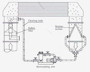
Figure 2 Sponge ball cleaning system (Taprogge)
6. Flow rates
To prevent floating particles from settling a minimum flow rate of 1,0 m/s should be maintained at every point of the equipment. Average water velocities of 1.5 to 2.0 m/s have been found to be successful. If water conditions are unfavourable it may be necessary to include special cleaning procedures at certain intervals, see corresponding section. To avoid erosion corrosion in 1" condenser tubes characterized by the protective layer being destroyed with subsequent local or uniform metal attack the following maximum flow rates should be maintained:
| Al Brass | max. flow rate | 1.9 m/s |
| 90-10 Cu-Ni | max. flow rate | 2.4 m/s |
| 70-30 Cu-Ni | max. flow rate | 2.9 m/s |
A reduction in maximum flow rate may be advisable, for instance, if abrasive solid particles are suspended in the water or if the tube diameter is much smaller than 1".
The above mentioned flow rate figures apply for tubes with a diameter of about 1". For seawater pipes, in general showing much larger sizes, faster flow rates are possible, following (25,26):
| Al Brass | 2.8 m/s |
| 90-10 Cu-Ni | 3.5 m/s |
| 70-30 Cu-Ni | 4.5 m/s |
| minimum flow rate for all sizes and alloys 1.0 m/s | |
For limited periods the flow rate can be doubled without any problems for the pipe material (Fire mains, cooling systems of submarines etc.)
7. Standby coolers
Standby coolers (and condensers) are occasionally duplicated for safety reasons, i.e. one unit is on standby and is not connected to the cooling circuit in service. However, standby coolers will generally have to be kept continuously ready for operation, with the required water filling. The following measures can be taken to maintain the tubes in proper condition:
- frequent changes between operational and standby cooler (e.g. every 2 to 3 days)
- short periodic water flushing with the full water quantity (also every 2 to 3 days)
- installation of a surge cleaning system.
Since the corrosion risk is higher for standby coolers it is recommended to clean them manually and more frequently and to inspect the tubes regularly (27).
8. Shutdown
Condensers are particularly at risk from corrosion underneath deposits during the starting-up period when a stable protective layer has not yet been formed. If a short shutdown (1 to 3 days) cannot be avoided, then the condenser may be left filled with clean cooling water if the tubes are free from deposits. Otherwise the contaminated cooling water should be drained and the tubes rinsed with clean water. Cleaning should also be carried out if the cooling water has a chloride content > 300 mg/I.
In case of longer shut-downs it is recommended not only to carry out the above mentioned procedures but also to ensure adequate ventilation of the tubes (opening of manhole covers and water chambers). The tubes should be dried by blowing in hot air if possible. It is also recommended to run the condenser dry with the manhole covers open. Water drainage and drying is facilitated by inclining the condenser. At certain intervals the tube surfaces should be checked visually to ensure that they are in satisfactory condition (27). Drying-out of the protective layer leads to cracking and spalling of the film. Such films have to be removed mechanically or chemically and must be redeveloped - as described - when the condenser is recornmissioned . To avoid this procedure it is sometimes easier to run the system with reduced cooling water flow rates, provided deposits can be prevented and it can be ensured that cleaning elements will not get stuck in the tubes.
In the case of ships' condensers where the flow rate depends on the ship's speed (natural circulation), an auxiliary circulation system should be installed so that the cooling water will circulate even at standstill or at very low speed.
9. Summary
To avoid early failures during commissioning, operation and after shutdowns on copper alloy heat exchangers the main objective is the formation and preservation of a sound protective surface layer. Which type of supportive measure is to be applied, i.e. Fe ++ dosage, mechanical cleaning and/or chlorination, and to what extent, depends on the individual conditions on site (water quality, type of equipment, operation mode etc.).
However it should also be noted, that most systems enter service with no special precautions and operate satisfactorily with no serious corrosion problems (1, 28).
In case of special questions operators should contact the manufacturer of the system as well as one of the individual national Copper Centres.
France - Centre d'lnformation du Cuivre, Paris
Germany DKI - Deutsches Kupfer lnstitut, Düsseldorf
Great Britain - Copper Development Association
Italy - istitutio ltaliano del Rame, Milan
Spain - Centro Espanol de lnforrncion del Cobre, Madrid
USA- Copper Development Association, Inc., New York
lnformations, drawings etc. in this publication are given to the best of our knowledge but without any liability whatsoever.
References
- B. Todd Nickel-Containing Materials in Marine and and Related Environments. 25th Conference of Metallurgists, Toronto, August 1986.
- B. Todd and P. A. Lovett Selecting Materials for Sea Water Systems. Marine Engineering Practics, Part 10. Institute of Marine Engineers,London
- P. Effertz and W. Fichte Die Eisensulfat-Dosierung in Kuhlsystemen - Grundlagen und Anwendung. VGB Kraftwerkstechnik, 57, Heft 2, Februar 1977.
- S. Sato and T. Nosetani Allowable Water Velocity and Cleanliness Factor of Aluminium Brass Condenser Tube with Ferrous Addition into Sea Water. Sumitomo Light Metal Technical Reports. 11(4), 1970.
- Brochures from Taprogge GmbH, 58300 Wetter, Germany. Systems for Cooling Water Circuits, 09.1996 / Taprogge Cleaning Balls, 08. 1995 I The Energy Saving Program, 05.1997 / The Combined Use of Taprogge Sponge Ball Cleaning and Ferrous Sulphate Injection, Technical Report 85 - 27, 08.1985 / Filter Technology, 09.1996.
- J. Castle and D. Epler ESCA Investigation of Iron-Rich Protective Films on Aluminium Brass Condenser Tubes. Corrosion Science, Vol. 16, 1976.
- F.P. ljsseling Rev. Corr. Coat.. 269 (1983)
- R. Francis Effects of Cooling Water Treatment on Ships' Condenser Tubes. BNF Research Report, No. 1945, January 1979.
- M. Jasner Korrosionsverhalten von Kupfer und Kupferlegierungen in Meerwasser. Fortbildungskurs am lnstitut für Schiffbau der Universität Hamburg, Mãrz 1988.
- E. Newton and J. Birkett Survey of Condenser Tube Life in Salt Water Service Arthur D. Little, Inc., Cambridge, USA, Aug. 1967.
- A. Cohen and P. F. George. Corrosion 74 / lnternat. Corrosion Forum, 143/1 -9, 1974
- 5. Henrikson et al. Report SVF-36, 1997.
- C. Pruvot Revue Generale Therm., 15, 503, 1976.
- R. Francis Effect of pollutants on corrosion of copper alloys in sea water. BCJ, 1985, Vol. 20, No.4.
- C. Christensen Proc. 7th Scandinavian Corrosion Conference, 1975.
- H. Ahrendt Seewasserführende Rohrleitungen an Bord von Schiffen der Bundesrnarine. HANSA - Schiffahrt-Schiffbau- Hafen, 111. Jahrgang, Heft 14, 1974.
- A.F.Stegelmann and R. Renfftlen On Line Mechanical Cleaning of Heat Exchangers, Hydrocarbon Processing, January 1983
- PT. Gilbert Use of Copper-Nickel Sheathing for Corrosion and Fouling Protection of Marine Structures. Marine Engineering with Copper Nickel, The Royal Institute of Metals, London, April 1988.
- C.A. Powell Preventing Biofouling with Copper Alloys. Copper Development Association, UK, Publication 113, July 1995.
- M.Jasner, R. Kircheiner, M. Rockel Results of Longtime Exposure of Copper-Nickel and Nickel-Copper Alloys in the North Sea. Marine Engineering with Copper-Nickel, The Royal Institute of Metals, London, UK, April 1988.
- S. Sato and K. Nagota Factors Affecting Corrosion and Fouling of Condenser Tubes of Copper Alloys and Titanium. NACE Conference, Corrosion in the Power Industry, Montreal, September 1972.
- C.A.PoweIl Corrosion and biofouling resistance of copper-nickel in offshore and other marine applications. UK Corrosion & Eurocorr 94,Bournemouth, November 1994.
- B. Todd and J.. Oldfield Corrosion and Chlorination in Materials for Offshore Seawater Systems. Chlorination of Seawater Systems and its Effect on Corrosion, Society of Chemical Industry, Bimingham, March 1986.
- Allianz Handbuch der Schadensverhütung, VdI-Verlag, Düsseldorf
- BS MA 18 August 1973, Salt water piping systems in ships
- DIN 81249 -2 (Draft) Corrosion of Metals in sea water and sea atmosphere Part 2: Free corrosion in seawater
- VGB - Richtlinie Rohre für Kondensatoren und andere Wärmetauscher. Teil A: Kupferlegierungen, VGB Kraftwerkstechnik, Essen, 1988.
- B. Todd Discussion in E.B. Shone and G.C. Grim 25 Years Experience with Sea-Water Cooled Heat-Transfer Equipment in the Shell Fleets. The Institute of Marine Engineers, London, November 1985.