Introduction
Traditional formed copper panel systems have demonstrated proven success as durable and effective exterior building cladding throughout recorded history. Both standing seam and flat seam copper systems continue to be utilized as a preferred roof covering and, increasingly as wall cladding.
While copper cladding systems obviously pass the test of time, modern design and construction standards have introduced quantifiable performance criteria, represented by mandatory requirements found in model building codes. As such, design professionals recognize a critical need to evaluate even time-tested, traditional building materials in accordance with modern experimental and analytical techniques.
Across the spectrum of stake holders - architects and engineers, contractors and building owners, fabricators and tradesmen – access to standardized technical data provides necessary assurances to support decisions regarding selection of materials and systems. In consideration of this, the Copper Development Association has undertaken a testing regimen with the goal of disseminating strength and serviceability performance data for common copper wall cladding systems.
The Systems
Copper provides a versatile, adaptable and durable material to create many discreate styles of wall cladding. While sheet copper is almost universally the standard raw material, cold-forming fabrication techniques range from exclusively traditional hand tools to modern non-motorized breaks, shears, and presses, to state-of-the-art rolling mills and computer controlled folding machines.
With this in mind, the initial phases of the testing regime focus on some of the most common and traditional styles of copper wall cladding. Common thickness of copper sheet (normally referred to as a weight, in ounces per square foot, of flat material) were utilized in the testing. As well, readily available copper alloys/treatments were selected. Finally, pre-manufactured panel clips and screws were used, in order to establish a consistent baseline for the panel attachment means and method.
It is a well-established practice to consider any performance results for tested systems as applicable to identical seam configurations from either heavier weight (thickness) copper sheet and/or narrower width panels.
The illustrations at the right depict systems tested to date.
Flat Lock Panel

- Horizontal & Diagonal
- 16 oz. (minimum) Copper
- Up to 21.75-inch width
- Up to 15.75-inch width for structural performance
Single Lock Standing Seam Panel

- Horizontal
- 16 oz. (minimum) Copper
- Up to 21.25-inch width
- Up to 15.25-inch width for structural performance
Double Lock Standing Seam Panel

- Vertical & Horizontal
- 16 oz. (minimum) Copper
- Up to 21.25-inch width
- Up to 15.25-inch width for structural performance
Test Standards
Each copper wall cladding system was tested to evaluate serviceability and structural performance. Serviceability includes the determination of rates of water and air infiltration through the cladding. Structural performance determines the system’s resistance negative wind pressures, as the wall cladding systems may be susceptible to suction forces, potentially causing “blow-off” during extreme wind events.
Rain Screen Design
Since the early 2000’s, design of exterior cladding systems according to the Rain Screen Principle has become a preferred design method. This principle, in short, considers the cladding to be an element of the exterior wall assembly that resists wind, ultra violet radiation, and other environmental conditions, while limiting moisture ingress into the wall assembly and promoting the drying of incidental moisture through drainage and ventilation of the wall cavity.
In recognition of this, the serviceability performance of these wall cladding systems was evaluated by the American Architectural Manufacturer’s Association (AAMA) 509 testing protocol entitled, Voluntary Test and Classification Method for Drained and Back Ventilated Rain Screen Wall Cladding Systems.
AAMA 509 results in classification of the cladding system based on both volume of water penetrating the cladding and contacting the air and water barrier element within the wall assembly, and the rate of air flow through the cladding joints and terminations. The water ingress is reported as a volume of water per unit area of cladding surface over a fixed time, expressed in units of ml/m2 (oz/ft2) and subsequently given a classification of W1 (least water penetration) to W11 (most water penetration). Ventilation is reported as a rate of air flow per unit area of cladding, expressed in units of L/s/m2 (cfm/ft2) and given a classification of V1 (least air flow) to V11 (most air flow). The AAMA 509 protocol consists of three separate testing procedures, detailed as follows.
American Society of Testing and Materials (ASTM) E283 Standard Test Method for Air Leakage through Exterior Windows, Curtain Walls, and Doors Under Specified Pressure Differences Across the Specimen determines the AAMA 509 air ventilation classification. For this procedure, each of four cladding element conditions are isolated and tested for air leakage. The conditions are vertical panel joints, horizontal panel joints, head flashing, and sill flashing.
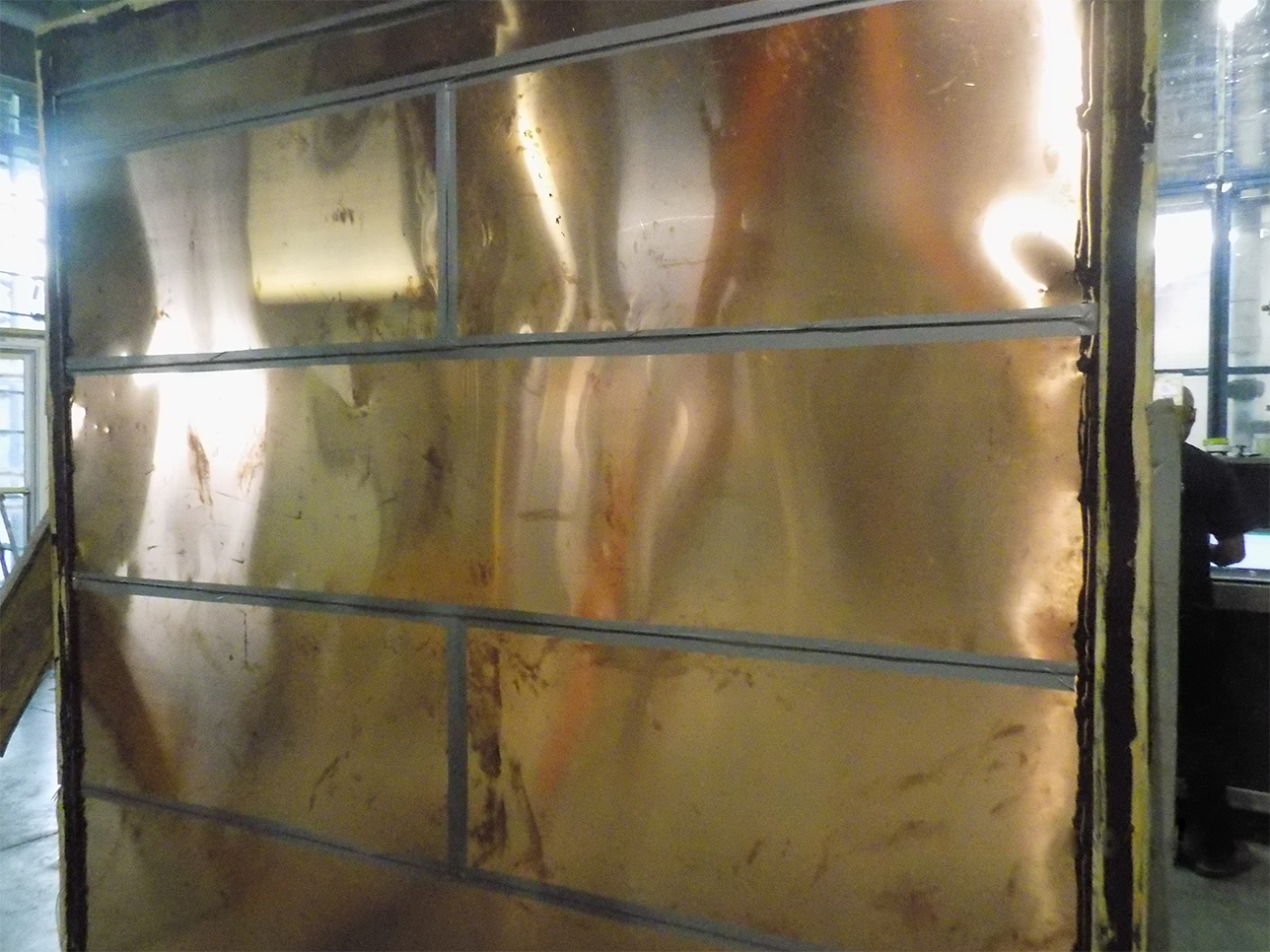
Figure 15.6.1: Horizontal copper flat lock panel with taped joints to isolate joinery elements for ASTM E283 air flow testing.
While higher ratings, representing higher rates of air infiltration, are desirable for rain screen cladding systems (as they promote greater potential for drying), lower ratings are preferable for traditional face-sealed cladding systems. Furthermore, the ventilation rating of a rain screen cladding system is generally evaluated to be “in balance” with the water penetration rating, i.e. a cladding that allows more water penetration may require a higher ventilation rating to adequately dry the wall cavity, whereas a cladding that allows virtually no water penetration may only require a minimal rate of air ventilation to dry the wall cavity.
ASTM E331 Standard Test Method for Water Penetration of Exterior Windows, Skylights, Doors, and Curtain Walls by Uniform Static Air Pressure Difference, is the first of two test methods used to determine the water penetration classification of a wall cladding, per the AAMA 509 protocol. This procedure applies a static inward (suction) pressure to the wall assembly, while subjecting the cladding to a direct water spray of 5 gallons per minute per square foot of cladding surface. The test is performed twice, once at 6.24 psf of static air pressure, and again at 12.0 psf of static air pressure. These pressures approximate the wind pressures associated with a severe thunderstorm and near-hurricane wind speeds, respectively. In order to insure that there is a suction pressure trying to draw water through the cladding seams and flashings, the air barrier material within the wall assembly is purposely made “faulty” by drilling holes through the air and water barrier until it is four times as “leaky” as is generally deemed acceptable.
After a 15-minute test duration, the volume of water penetrating the cladding and reaching both the exterior and interior face of the air and water barrier is collected by drainage channels built into the test specimen. The collected water volume is measured and recorded.
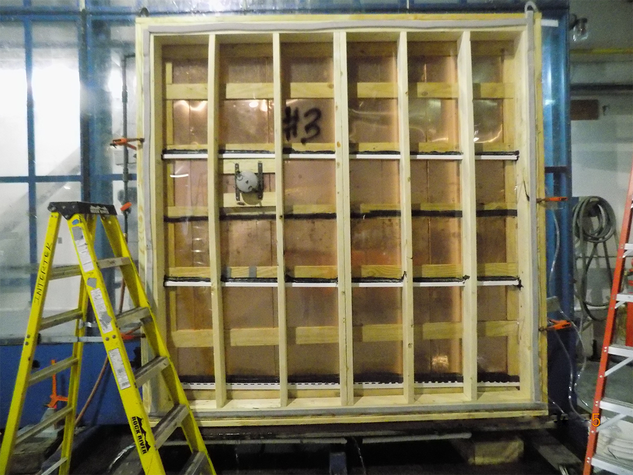
Figure 15.6.2: Vertical copper double lock standing seam. View from inside face of wall assembly during ASTM E331 water penetration test.
AAMA 501.1. The second water resistance test standard, developed by the American Architectural Manufacturers Association is entitled Standard Test Method for Water Penetration of Windows, Curtain Walls and Doors Using Dynamic Pressure. Unlike virtually all other cladding testing methods, this procedure subjects the wall assembly to significantly more realistic wind and water conditions by utilizing a propeller engine to generate a dynamic, and yet calibrated, wind stream.
As with the ASTM E331 test, the procedure is performed twice on each specimen, at 6.24 psf and 12.0 psf of static air pressure. These pressure magnitudes are correlated to an equivalent wind velocity of 50 mph and 69 mph, respectively. This procedure is ideal performed on an outdoor testing apparatus that is, for obvious reasons, well braced against toppling over from the direct force of the wind.
Once again, a 5 gallon per minute per square foot water load is injected into the air stream and applied against the cladding panel specimen for 15-minutes. Water passing through the exterior cladding and impacting the air and water barrier within the wall assembly is collected, measured, and recorded.
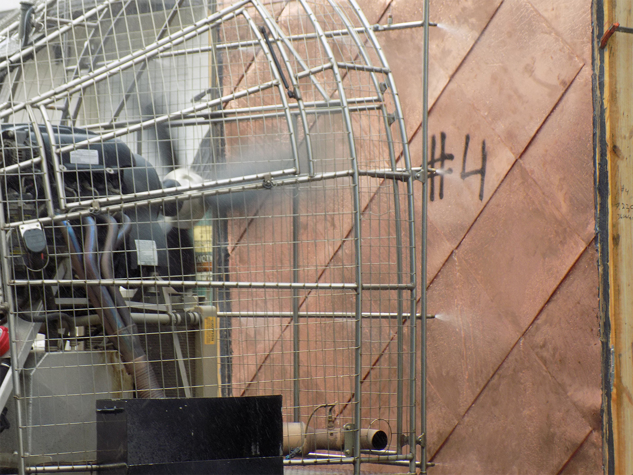
Figure 15.6.3: Diagonal copper flat lock cladding tested by the AAMA 501.1 dynamic pressure water penetration procedure.
Wind Resistance. In addition to the serviceability considerations examined by the air and water testing procedures, a key criterion for any wall cladding design is capacity to resist negative pressure generated by wind forces. During an extreme weather event, buildings may experience severe wind from any direction.
While the wall cladding on the windward face experiences an inward pressure, the true test of a cladding system occurs on the opposite face of the building. On the leeward wall, wind forces will create a negative suction pressure, attempting to tear the cladding panels away from the structural wall supports. The negative suction pressure is greatest at vertical edges of the wall (corner strips), and the pressure increases with the height of the wall.
ASTM E330. Standard Test Method for Structural Performance of Exterior Windows, Doors, Skylights and Curtain Walls by Uniform Static Air Pressure, Utilized to determine the wind pressure capacity of the copper wall cladding panels, and their attachment to the supporting wall assembly. For this procedure, the cladding system is installed on a representative supporting wall structure. For the copper wall cladding systems, plywood furring strips were used to represent typical wall sheathing installed behind copper wall systems.
For this procedure, a thin plastic film is installed between the wood sheathing strips and the copper cladding panel in order to direct all air pressure load to the copper panels, without any aid from other components of the wall assembly. In this respect, the procedure is known to provide conservative results of the wall assembly capacity. Once assembled, the specimen is subject to loading and unloading cycles, with each successive load incremented to a higher and higher level. Each load is maintained for at least 30 seconds before unloading the specimen and proceeding to the next cycle. The test is concluded only after the specimen experiences a structural failure and can no longer resist the applied load.
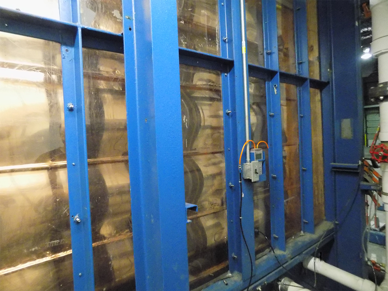
Figure 15.6.4: Horizontal single lock standing seam cladding tested for wind resistance according to the ASTM E330 test method.
The results of the ASTM E330 test are reported as a negative wind load, expressed in pounds per square foot (psf) of air pressure, at the point of structural failure of the cladding system. The panel clips and attachment screws are subjected to the applied test loads and become tested system components. The supporting sheathing and wall structure is not evaluated by the test method, and may be designed using customary analysis techniques.
Results
Horizontal Flat Lock Copper Panel
- AAMA 509 D&BV Rain Screen: V1/W1 Classification
- ASTM E283 Air Infiltration: 1.39 cfm/ft2 (7.05 L/s/m2) at 1.57 psf
- ASTM E331 Water Penetration: 0.00 oz/ft2 (0.31 ml/m2) at 6.24 psf 0.00 oz/ft2 (0.31 ml/m2) at 12.0 psf
- AAMA 501.1 Water Penetration: 0.00 oz/ft2 (0.00 ml/m2) at 6.24 psf 0.01 oz/ft2 (4.07 ml/m2) at 12.0 psf
- ASTM E330 Negative Wind Load: 85.20 psf (4,080 Pa)
Diagonal Flat Lock Copper Panel
- AAMA 509 D&BV Rain Screen: V1/W1 Classification
- ASTM E283 Air Infiltration: 0.42 cfm/ft2 (2.12 L/s/m2) at 1.57 psf
- ASTM E331 Water Penetration: 0.00 oz/ft2 (0.00 ml/m2) at 6.24 psf 0.00 oz/ft2 (0.77 ml/m2) at 12.0 psf
- AAMA 501.1 Water Penetration: 0.00 oz/ft2 (0.77 ml/m2) at 6.24 psf 0.04 oz/ft2 (12.66 ml/m2) at 12.0 psf
- ASTM E330 Negative Wind Load: 208.00 psf (9,860 Pa)
Single Lock Copper Standing Seam
- AAMA 509 D&BV Rain Screen: V1/W1 Classification
- ASTM E283 Air Infiltration: 0.40 cfm/ft2 (2.04 L/s/m2) at 1.57 psf
- ASTM E331 Water Penetration: 0.06 oz/ft2 (19.02 ml/m2) at 6.24 psf 0.06 oz/ft2 (19.41 ml/m2) at 12.0 psf
- AAMA 501.1 Water Penetration: 0.03 oz/ft2 (9.66 ml/m2) at 6.24 psf 0.04 oz/ft2 (12.66 ml/m2) at 12.0 psf ASTM E330 Negative Wind Load: 80.00 psf (3,830 Pa)
Double Lock Copper Standing Seam
- AAMA 509 D&BV Rain Screen: V1/W1 Classification
- ASTM E283 Air Infiltration: 0.42 cfm/ft2 (2.14 L/s/m2) at 1.57 psf
- ASTM E331 Water Penetration: 0.00 oz/ft2 (0.00 ml/m2) at 6.24 psf 0.00 oz/ft2 (0.00 ml/m2) at 12.0 psf
- AAMA 501.1 Water Penetration: 0.01 oz/ft2 (2.30 ml/m2) at 6.24 psf 0.02 oz/ft2 (6.06 ml/m2) at 12.0 psf
- ASTM E330 Negative Wind Load: 127.70 psf (6,1150 Pa)
Table 15.6.1: Maximum Wall Height Based on Negative Wind Pressure
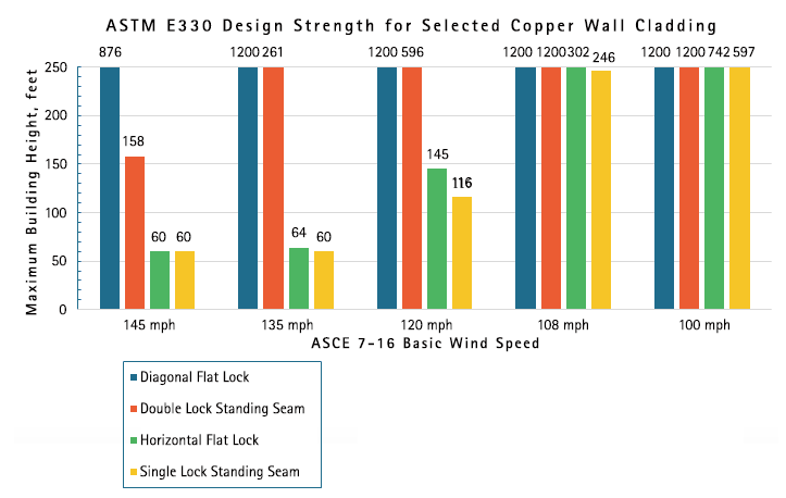
This chart is provided for general illustrative purposes only. A qualified design professional must evaluate project specific applications. Project specific performance testing and/or wind tunnel modeling may be for design loads which exceed the limits of current testing. Increased capacity may be achieved through heavier copper material, narrower panel width, and/or alternate means of attachment, please contact the Copper Development Association for additional assistance.
The maximum building height is based upon a Component and Cladding Zone 5 wind pressure of a Risk Category II building in an Exposure Category B as per ASCE-7-16.
The system design capacity is based upon ASTM E330 test results. A resistance factor of 0.80 has been applied to the maximum tested load.
Refer to specific ASTM E330 test for system details such as max. panel width, max. clip spacing and min. material thickness.