- Important Management Support
- Real Problem: Poor Grounding
- Total System Upgrade
- Less than One Ohm!
- Copper Ground Bus
- More and Better Bonding Indoors
- 9-1-1: Ready When Needed
- 9-1-1 To Go
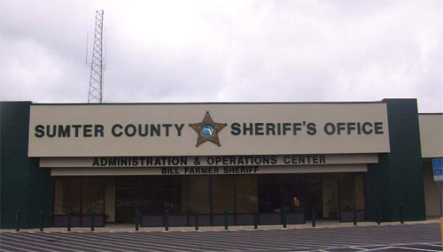
A few years ago, the Sumter County, Florida government took over what had been a 55,000-sq ft. Walmart store in the city of Bushnell. Walmart wanted to build a larger outlet nearby and the county badly needed office space, so the deal was a win-win situation. The building is now the spacious new home for several county offices, including those of the Sheriff’s Department (photo below).
Important Management Support
But there was a catch: the key component of any sheriff’s department is its communication center, including the all-important 9-1-1 hub and dispatch room. Sumter County’s problem was that its new 9-1-1 center is located smack in the heart of the most lightning-prone region in the entire country, Florida’s notorious “lightning alley”, yet the building’s electrical and grounding systems were built for a 1970s-vintage department store!
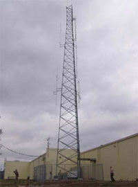 Figure 1. At the Brewster Earth Station, Verestar operates C-, C/L- and Ku-band antennas ranging in size from 3.5 to 30 meters. Some are fixed, but most are agile. All antennas are grounded either through their structures, through the sheath on the coaxial cable linking them to the communications facility, or both.
Chief Deputy Sheriff Jack Jordan knew the problem personally. He was on duty in 2004 when a lightning strike to the county’s previous communications center took out all 9-1-1 communications, as he puts it, “right when we needed a 9-1-1 center!” The seriousness of the situation wasn’t lost on the Chief Deputy Sheriff, and good things generally happen when top management recognizes a problem.
The first priority was to get the building remodeled and move in. The old electrical system, built for a department store, was upgraded at the same time. The structure had dual 480-V services plus two emergency generators, but right there was the tip of an iceberg of trouble: The two electrical systems were independently grounded, each with its own ground rod. That’s not good design, so the systems were combined and grounded to one of the existing galvanized steel electrodes.
A 121-ft. communications tower, Figure 1, was erected in 2007, and the 9-1-1 center was occupied the following year, including fire, police, weatheralert and other public-safety communications facilities.
Fortunately, Chief Deputy Sheriff Jordan had the technical talent on board to see where improvements were needed. He directed his communications chief, Administrative Lieutenant Russell G. Merritt and Marie Keenum (ENP), Sumter County’s 9-1-1 Coordinator, to evaluate the electrical and grounding systems thoroughly. Keenum, who experienced the previous lightning damage event, and Merritt, a retired Army Sergeant Major with a career’s worth of experience in communications, saw serious problems. They recommended that the county seek professional help.
Marie Keenum had previous experience working with, and therefore selected, John West, president and founder of Power & Systems Innovations, Inc., an Orlando-based company that specializes in power quality improvement, grounding and lightning-protection system design. Mr. West and his company are well known in lightning alley, having upgraded several regional emergency facilities similar to those in Bushnell. West acted as consultant and project manager and hired Rick Thompson, president of Power Quality Solutions, Inc., to plan and install an upgraded system. Good things were starting to happen.
Back to TopReal Problem: Poor Grounding
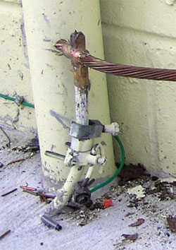 Figure 2. When combining the former Walmart’s two power services, electricians transferred the grounding system to one existing galvanized steel electrode. Ground resistance at the electrode was 230 Ω, which is far too high for a sensitive communications facility.
- The new transmission tower also had its own independent grounding system consisting of an electrode and a ring ground that was not directly connected to the building’s service entrance ground. Again, independent grounds should not be used, since, in communications systems, they are a fertile source of noisy ground-loop currents. Thompson also found that coaxial cable leads connecting antennas on the tower with the comm center were not grounded. Had lightning struck the tower, it would have had a direct, high-conductivity path into communications equipment.
- The grounding electrode system for the building itself consisted of a single galvanized steel electrode installed in the 1970s, Figure 2. Thompson measured resistance to ground at the electrode and found that it registered 230 Ω, which is way above the five-ohm maximum cited in IEEE recommended practices and nearly ten times higher than the 25-Ω limit noted in the National Electrical Code® for a single electrode.
- The two emergency generators were also independently grounded. The grounding conductor bond at one generator was in questionable condition, Figure 3, and the other one used an automotive hose clamp (a fairly common but definitely very poor practice).
- Rainwater had penetrated the 480-V service entrance panels, corroding fuse connections. The panels themselves were not bonded to ground, another issue left over from the days when the building was a retail facility. It had to be corrected.
- Panels and sub-panels in the main electrical closet were protected by a combination of lightning arrestors and surge protection devices (SPDs). It isn’t known if lightning ever did enter the building, but at least one of the lightning arrestors at the service entrance was damaged and one of them had been replaced (note the black mark on the electrical panel, Figure 4, showing evidence of the device failure). SPDs are supposed to shunt voltage spikes to ground. They can’t do that when they’re not well grounded.
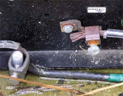 Figure 3. Two emergency generators were independently grounded via galvanized steel electrodes, one of which is shown at the left of the photo. Bonded connections were not in good condition, and one (not shown) utilized a commercial hose clamp to secure the connection.
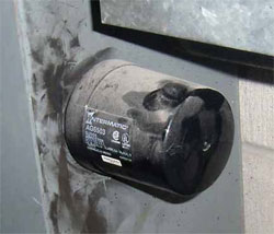 Figure 4. Soot smudges indicate that this SPD on a sub-panel had sustained some damage, possibly lightning-induced. SPDs must be very well grounded in order to work. This one wasn’t. The building’s two distribution transformers were supposedly grounded to building steel. However, building steel was not bonded to the building’s old grounding electrode, as it should have been.
 - The building’s two distribution transformers were supposedly grounded to building steel. However, building steel was not bonded to the building’s old grounding electrode, as it should have been.
- In the transmitter rooms, contractors had “daisy-chained” ground leads from several pieces of equipment to common grounding points. That’s a shortcut, but it adds resistance and potential ground loops to the ground path.
Total System Upgrade
Mr. Thompson designed the new grounding system shown in Figure 5. Chief Deputy Sheriff Jordan authorized work to begin immediately. The cost, between $38,000 and $40,000, was tiny compared with the improved public safety it bought for Sumter County’s 98,000 inhabitants.
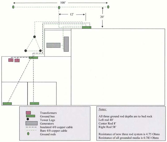 Figure 5. Important improvements to the communications center’s new grounding system included extremely low resistance thanks to three deep electrodes and a robust copper ring ground. Equally important are the systems large-gauge conductors, use of proper bonding practices throughout, and a well-engineered layout based on a central grounding bar.
Less than One Ohm!
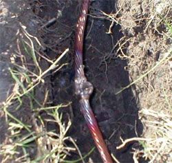 Figure 6. Three electrodes, one at each tower leg, were exothermally bonded to an AWG 4/0 bare copper ring ground. The ring and its deep-driven electrodes served as the main earth connection for the new system.
Transmission Tower & Ring Ground. Thompson began the upgrade at the tower. He installed three new copper-clad electrodes, one at the base of each tower leg, at depths of 40 ft., 8 ft. and 58 ft., respectively. The deep electrodes would ensure low resistance. He exothermically welded an AWG 4/0 bare copper ring ground to the electrodes, Figure 6, then ran AWG 4/0 pigtails to the tower and external system elements and surrounded the conductors with bentonite, Figure 7. Bentonite is a clay mineral that expands when moistened, making good contact to earth. It also protects copper against corrosion over a wide range of soil conditions.
To bond grounding conductors to the tower legs, Thompson first welded ¼-in steel tabs to the tower legs, then exothermally welded the 4/0 to them, Figure 8. (The welds were sprayed with protective paint.) The bonds are robust and are easy to inspect and service if needed.
Coax Shields. Coaxial cables originating at antennas on the tower weren’t grounded, so Thompson installed a copper ground bar on the tower above the point where the cables make a 90° turn to the ice bridge and toward the building bulkhead, Figure 9. He bonded short copper leads to shields on the waveguides, then double-lugged them to the ground bar. The leads slope downward to keep the path toward earth as direct as practical. Similarly, a length of 4/0 (encased in PVC conduit) extends straight down from the ground bar to the buried ring.
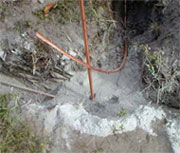 Figure 7. The electrodes, ringground and other conductors were surrounded by bentonite, which lowers resistance by providing good contact with the soil. It also protects copper over a wide range of soil conditions. A portion of the ring is at lower left. The copper-clad electrode, center, is ready to be welded to one of several AWG 4/0 bare copper pigtails that extend to the tower legs and external system elements.
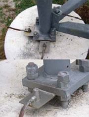 Figure 8. AWG 4/0 conductors extending from the ring ground were exothermally bonded to ¼-in steel tabs that had been welded to each tower leg. Conductors are bare copper. Spray paint protects the underlying steel.
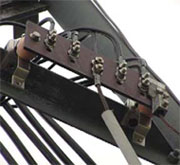 Figure 9. Shielding on coax is grounded by leads (thin conductors, upper left) to the copper ground bar shown in the photo. The bar itself is grounded via a conduit-enclosed, vertical conductor that extends to the tower’s ring ground, below. Conductors are run as straight downward as practical to direct lightning energy toward earth. Double lugs and lock nuts on the ground bar add reliability in this difficult-to-service location.
Horizontal Electrode. Thompson laid 100 ft. of AWG 4/0 bare copper grounding conductors in a two-foot-deep trench running parallel to, and approximately 20 ft. behind, the main building, Figure 10. The copper, which is bonded to the ring ground, serves as a horizontal grounding electrode to direct lightning energy from away from the tower and building. The buried copper may also have helped reduce the system’s ground resistance.
Emergency Generators. The facility has two propane-fueled emergency generators, rated at 150 kVA and 40 kVA. Thompson ran AWG 4/0 copper from the ring ground to the generators, overlapping flimsy existing grounds, Figure 11. He also grounded the generators’ propane fuel line, securing all conductors to the concrete slabs with Hilti nails, which are stronger and more tamper-resistant than screws.
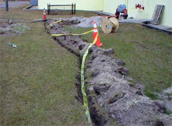 Figure 10. A 100-ft. trench containing AWG 4/0 bare copper constructed approximately 20 ft. behind and parallel to the main building. The buried copper directs lightning energy away from the tower and the building.
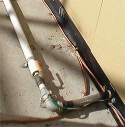 Figure 11. New AWG 4/0 grounding conductors connect the ring ground and the emergency generators. A conductor is also bonded to the generator’s propane fuel line. Tamper-resistant Hilti nails secure the conductors to the concrete slab.
Copper Ground Bus
Grounding electrodes are normally driven at or near a facility’s electrical service entrance. That was the case for the original grounding system at the former Walmart store. Thompson bonded to the old rod, but used the deep, low-resistance electrodes and ring at the nearby tower as the primary earth connection.
Connections from the ring and from all other grounding conductors, including the groundneutral bonds in the service entrance, were routed to a ¼-in. thick grounding plate mounted on standoffs on the building wall below the dual service entrance cabinets, Figure 12, which, in turn, was connected to the facility’s main grounding bus ― another copper plate ― on the exterior wall below the waveguide entrance bulkhead, Figure 13. Also bonded to the lower ground bar was the building’s original grounding electrode and two new Transguard TG100 SPD units, one for each service entrance cabinet. The TG100s are rated to 100 kA line-to-neutral and line-to-ground, and 200 kA per phase.
It is absolutely imperative that SPD devices be reliably grounded and that the resistance to ground (earth) be as low as possible. SPD devices cannot function if they are not well grounded.
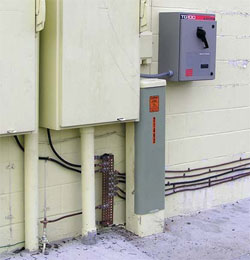 Figure 12. All ground leads meet at a ¼-in thick copper ground bar below one of the building’s service entrance cabinets. Also bonded to the bar are the building’s original ground rod, lower left, and two newly installed Transguard TG100 surge suppressors, one of which can be seen at upper right.
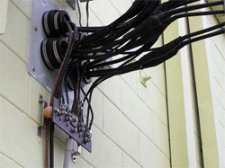 Figure 13. The facility’s main grounding bus is mounted on an exterior wall, directly beneath the waveguide bulkhead. The bus connects to the ground plate shown in Figure 12 and to the main indoor ground bus directly behind it.
More and Better Bonding Indoors
Indoors, Thompson concentrated on distribution transformers, sub-panels, and communications and computer racks in equipment rooms.
- He first installed a ground bar indoors, aligned approximately back-to-back with the main (outdoor) grounding bus, Figure 14. It serves as the collection point for grounding conductors from panels, sub-panels and additional ground bars in equipment rooms.
- The site’s two distribution transformers had been “grounded” to building steel, but the steel was not bonded to the grounding electrode. Thompson grounded them properly with AWG 4/0 copper, Figure 15, which he ran directly to the main facility grounding bus outside using one of the four bulkhead penetrations.
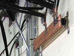 Figure 14. The main indoor grounding bus is mounted approximately back-to-back with the main bus outside. It serves sub-panels and ground bars in equipment rooms. The four bulkhead penetrations can be seen directly above the bus. Grounding conductors from the transformers are threaded through one of those penetrations and are bonded directly to the main bus.
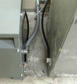 Figure 15. Distribution transformers that had been “grounded” to building steel were properly bonded to the main outdoor grounding bus with AWG 4/0 copper (black cables at center).
 - Technical Electric Systems fitted panels and subpanels with new SPDs, examples of which are shown in Figures 12 and 16. The intent here was to provide multi-layered SPD protection, i.e., at the service entrance, at the main distribution panel indoors, at sub-panels and, finally, at load points such as computer terminals downstream. Surge protection was installed by Mike Henry of Technical Electric Systems, Inc.
- Lastly, Thompson attacked the hodgepodge of grounding that he, John West and Lieutenant Merritt had found in communications equipment rooms, on transmitters, routers, and other gear. He replaced the daisychained grounds with homeruns to grounding plates and installed a separate grounding plate for coax shields at the point where they enter the radio room, Figure 17. That provided redundant protection since the coax cables were also grounded at the the tower (Figure 9), thus providing two points at which lightning energy could be shunted away from communications equipment.
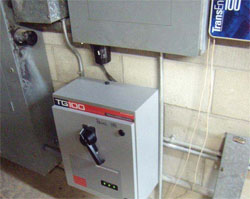 Figure 16. The comm center’s multi-layer surge protection is illustrated by the large-capacity TG100 SPD, which serves the entire electrical closet, and a smaller TS100, mounted on a subpanel. Both are rated at 100 kA line-to-neutral and line-to-ground, and 200 kA per phase. Black modules are older SPD units which were left in place. Surge protection was installed by Mike Henry of Technical Electric Systems, Inc. Note the black mark on the electrical panel at far left, which shows where an old lighting arrestor failed and was replaced at some time in the past.
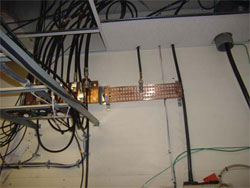 Figure 17. A copper ground plate, right, collects equipment grounding conductors in the center’s radio room. A separate plate, behind racks at left) is bonded to shields on coax cables entering from above.
9-1-1: Ready When Needed
With the lives of 98,000 Sumter County residents at potential risk, there is no question that the 9-1-1 system upgrades were worth the cost. There have been no disruptions since the upgrades. Chief Deputy Sheriff Jordan and the citizens his department serves can now rest assured that they’ll have reliable communications “right when a 9-1-1 center is needed”.
9-1-1 To Go
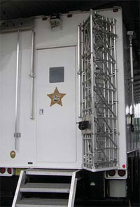 The Sumter County Sheriff’s Department does not rely solely on its new communications center in times of emergency. When times get really rough, such as during hurricanes, the department sends out its mobile 9-1-1 center, an 18-wheeler equipped with all the communications gear needed to handle protracted blackouts. The mobile unit mounts several collapsible antennas, and yes, it is fitted with provisions to attach a low-resistance grounding electrode. Even here, grounding is recognized as the key to reliable communications.
The Principals
 Jack Jordan (Sumter County Chief Deputy Sheriff) was the driving force behind the system upgrade described in this case study.
 Marie Keenum is the 9-1-1 coordinator for Sumter County, including all municipalities in the jurisdiction. Ms. Keenum personally experienced the lightning strike to the previous dispatch center and was instrumental in coordinating the upgrade to the new one.
 Rick Thompson is founder and president of Power Quality Solutions, Inc., the principal designer and installer of the grounding system upgrade at the Sumter County Sheriff’s Department communications center. Mr. Thompson can be reached at (407) 469-2905, cell (321) 689-7759, and [email protected].
 John West, Sr. is President of Power Systems & Innovations, Inc. (PSI), Orlando, Florida. Founded in 1992, PSI provides products, services and consulting related to power quality, power protection, surge protection, grounding, lightning protection and other anomalies that can damage equipment and/or cause data loss. Contact Mr. West at [email protected] or (407) 380-9200.
 Mike Henry is Principal and Owner of Technical Electric Systems, Inc., Debary, Fl. The company, which specializes in challenging assignments such as the one described here, installed surge protection systems now in use at the Sumter County Sheriff’s Department headquarters. Mr. Henry can be reached at (386) 668-0691.