by Wilhelm Schleich; Paper No 5222; CORROSION/2005; Houston; ©NACE International.
Abstract
Over several decades, many thousand of tons of the copper-nickel alloy UNS C70600 have been used as a seawater piping material in marine engineering. In order to provide reliable service performance of the material, this paper discusses its metallurgical properties, the relevant mechanisms of general, localized and erosion corrosion, the unique biofouling resistance and the performance in polluted water. The guidelines for the production of UNS C70600 products, the design of pipe work, the limits of the alloy and useful service recommendations are outlined.
Introduction
The choice of an appropriate material for seawater service is a difficult decision that has to be made by a designer prior to specification of the system. Since a broad range of conditions will usually be imposed on the piping material, the impact of seawater on material performance is determined by numerous variables such as condition of the material, system design, fabrication procedure, various seawater temperatures and flow regimes, biological activity, and presence of oxidizing compounds. Further factors that are relevant in choosing a material for a seawater piping system are: physical and mechanical properties, availability, material costs, ease of fabrication and maintenance, anticipated design-life and previous design experience. Over several decades, many thousand of tons of the copper-nickel alloys UNS C71500 and UNS C70600 have been installed in different marine engineering structures for the shipbuilding, offshore, power and desalination industries. These alloys, which have been applied for seawater piping and heat exchangers, are adopted by various standards. UNS C71500 is predominantly used for military submarine service due to its higher strength and maximum allowable flow rate, as well as low magnetic permeability. However, the wider commercial application of this alloy is limited to a certain extent because of its higher material cost. The work-horse, therefore, is the UNS C70600 (CuNi 90/10, cupronickel). This alloy reveals a well-balanced combination of characteristics allowing its widespread and economical use. To ensure the further reliable application of the material, there is a need for a detailed discussion on its properties. In particular, attention should be drawn to the quality of CuNi 90/10 products, the performance in waters containing hydrogen sulfide and the prevention of erosion as well as galvanic corrosion. This paper is based on a literature review and experience of KME as a manufacturer of copper-nickel piping systems. It describes the relevant corrosion mechanisms and provides useful service recommendations particularly for UNS C70600.
Corrosion and Biofouling Resistance
Metallurgical Considerations
Copper and nickel have similar atomic radii and lattice parameters and so the phase diagram is relatively simple (Figure 1)1. At all temperatures, Cu-Ni alloys are represented by a single phase face centered cubic structure. The absence of phase transformation during thermal cycles reduces the effect of welding on mechanical characteristics and the corrosion resistance of the material. This crystallographic structure reveals very good ductility and impact strength even at temperatures well below freezing point. The slow diffusion rate for nickel in copper leads to concentration gradients in the melt and consequently increases a segregation tendency in the cast structure at normal cooling rates (Figure 2). Thus, to provide a uniform establishment of protective oxide layers, the homogenization of the segregated structure is required by hot forging or cold working with a subsequent recrystallisation anneal.2
Table 1 compares the common international compositional standards for cupronickel. Some specifications monitor more strictly the iron content which is an essential alloying element and responsible for the improvement in corrosion resistance of the alloy. The alloying range between 1,5 and 2,0 wt.% Fe provides optimum resistance in flowing seawater (Figure 3)3. To provide the appropriate quality of cupronickel products, the cooling rate from the solution annealing temperature must keep the precipitation of iron containing particles to a minimum. The quality of the piping can be easily assessed by measurement of the relative magnetic permeability, which should be lower than 1.5.4 As for all metallic materials, if the CuNi 90/10 has to be welded, the maximum limits for some impurities such as lead, sulfur, carbon, and phosphorus should be carefully controlled.
 Figure 1. Phase diagram for Cu-Ni alloys.
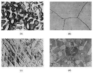 Figure 2. The matrix of UNS C71500 etched with FeCl3, (a) cast, (b) cast and annealed at 1100°C/ 30 min, (c) cast, 50% cold worked, and annealed at 850°C/ 4 h, (d) cast, 50% cold worked, and annealed at 850°C/25 h.
| Standard | DIN/EN | ASTM | ISO | EEMUA | KME |
|---|---|---|---|---|---|
| Designation | CuNi10Fe1Mn | CuNi10Fe1Mn | CuNi10 Fe1,6Mn | ||
| Ref. No. | 2.0872/CW352H | UNS C70600 | UNS 7060X | ||
| Copper | Rem. | Rem. | Rem. | Rem. | Rem. |
| Nickel | 9.0-11.0 | 9.0-11.0 | 9.0-11.0 | 10.0-11.0 | 10.0-11.0 |
| Iron | 1.0-2.0 | 1.0-1.8 | 1.0-2.0 | 1.5-2.00 | 1.50-1.8 |
| Manganese | 0.5-1.0 | 1.0 | 0.5-1.0 | 0.5-1.0 | 0.6-1.0 |
| Tin | 0.03 | - | 0.03 | - | 0.03 |
| Carbon | 0.05 | 0.05 | 0.05 | 0.05 | 0.02 |
| Lead | 0.02 | 0.02 | 0.02 | 0.01 | 0.01 |
| Phosphorus | 0.02 | 0.2 | 0.02 | 0.02 | 0.02 |
| Sulphur | 0.05 | 0.02 | 0.02 | 0.02 | 0.005 |
| Zinc | 0.05 | 0.5 | 0.5 | 0.2 | 0.05 |
| Cobalt | 0.1 | - | 0.05 | - | 0.1 |
| Impurities | 0.2 | - | 0.1 | 0.3 | 0.02 |
| Single values represent the maximum content. | |||||
 Figure 3. Influence of iron content on depth of impingement attack on UNS C70600 in seawater after 30 days duration test at 3 m/s.3
As a confirmation of above considerations, Figure 4 one of many weld necks installed on an offshore unit operating off the coast of South America. A great number of weld necks downstream valves and pumps suffered corrosion attack. The system was operated at ambient temperature and at a flow rate below 3,5 m/s. The cross-section of the weld neck shows a cast structure. The chemical analysis of the weld neck revealed the presence of 0.952 % Fe, 0.012 % Mn, and 0.087 % S.
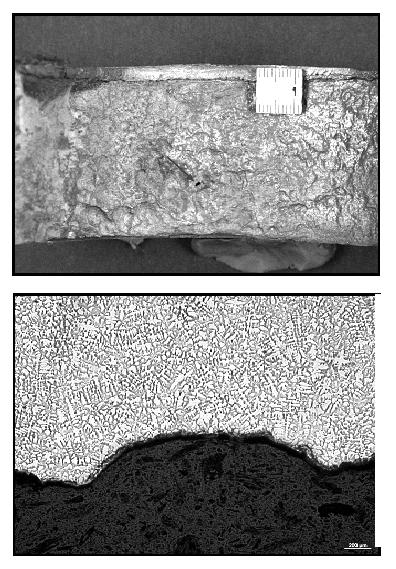 Figure 4. Erosion corrosion damage of the inner surface of the weld neck (left), cross section of the weld neck demonstrates a cast structure of the compound (right).
General Corrosion
The corrosion behavior of copper-nickel depends on the presence of oxygen and other oxidizers because it is cathodic to the hydrogen electrode. During the primary corrosion reaction, a cuprous oxide film is produced that is predominately responsible for the corrosion protection. The products of corrosion reactions can react with compounds in seawater e.g. to CuCl23Cu·(OH)2 or Cu2(OH)3Cl and in so doing build a multi-layered oxide structure. The corrosion rate quickly decreases significantly over a few days, with one study indicating that the associated discharge of copper ions was reduced tenfold during 10 min and 100-fold in the first hour.5 The long-term general corrosion rates of UNS C70600 have been found to continuously decrease with time of exposure to below 2.5 µm/yr.6 However, establishment of a mature film takes from 2 7 to 35 months at temperatures of 15-17°C. At 27°C, common inlet temperature for the Middle East, the establishment of the protective film within a few hours was reported.8 In spite of a wide utilization of cupronickel, the positive effect of the seawater temperature9 is still not well understood and more research is required on this area.
It is important to ensure appropriate formation of the protecting film and, thus, to avoid premature failures. The following recommendations work well during hydrotesting and commissioning:
- The system should be cleaned from dirt, lubricants and debris. Introduction of solid matter should be avoided by installation of strainers or screens.
- The usage of clean seawater or fresh water for hydrostatic testing is advisable. If polluted water has been used, it should be disposed and the pipe work should be rinsed properly with clean seawater or fresh water. If subsequent stagnant conditions are expected, blow-drying of the system is advisable.
- During commissioning of a new or retubed system, continuous exposure to clean seawater for up to 3 months, depending on water temperature, is needed to establish a mature protective film.
- A system with continuous pumping activity, such as a cooling system, can be commissioned under normal operating conditions. In seawater and water containing high levels of suspended matter, the minimum flow rate should not be below 0.5-1 m/s in order to prevent the formation of deposits.
- The commissioning of a system with intermittent flow, such as a fire fighting system, should be conducted in seawater free from suspended matter, e.g. in water from the open sea. However, the seawater has to be replaced by oxygenated seawater within 4-5 days to avoid putrefaction.10
Biofouling
The bacteriostatic properties and resistance of cupronickel to macrofouling are well recognized and widely used.11 There are two different aspects to which these characteristics can be attributed:
On the one hand, there is a gradual release of cuprous ions that is not tolerated by many marine organisms. It has been shown, that the establishment of a bacterial layer on the surface of cupronickel is significantly retarded. The natural corrosion rate of cupronickel is sufficient to decelerate the initial development of the biofouling layer.
On the other hand, the cupronickel generates a passive film, which consists of several different layers. A thin cuprous oxide layer, which is formed on the bulk metal, provides sufficient corrosion resistance. The top layers, which are formed during secondary corrosion reactions, have a weakly adherent porous structure which reduces the release rate of cuprous ions. This may allow some organism settlement to take place on the surface in quieter conditions although, due to the weak adherence of the top layers, biofouling sloughs off periodically revealing the protective inner cuprous oxide layer again.
Figure 5 compares the appearance of cupronickel and steel plates exposed under similar conditions.12 The significant difference in the accumulation of biological mass on steel samples is evident. Costly cleaning procedures and chlorine treatment of seawater become unnecessary. However, it has been widely recognized that, if cathodically protected, the biofouling resistance of cupronickel is decreased.
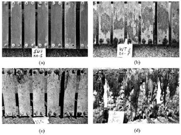 Figure 5. (a-c) UNS C70600 samples after 2 years exposure to different environmental zones at Helgoland, North Sea: (a) Splash, (b) Tide, (c) Submersed, (d) structural steel after 1 year of exposure at the same location under fully immersed conditions.
Localised Corrosion
In clean natural seawater or in seawater chlorinated to levels sufficient to control the biological metabolism, UNS C70600 is resistant to localized attack. Due to its biofouling resistance, the number of potential sites for pitting attack is limited, even in slowly moving seawater. However, in polluted water containing hydrogen sulfide, pitting usually takes place in the form of wide and shallow pits. The undercut type of pitting attack normally associated with stainless steel is not common for CuNi 90/10.
Only a limited amount of information is available on failures of copper-nickel due to crevice corrosion.13 Theoretically, the crevice corrosion behavior of the alloy is generally controlled by an ion concentration cell mechanism where the accumulation of copper ions in the crevice leads to ennoblement. Thus, if encountered, the corrosion attack would tend to take place in the region adjacent to the crevice, which is exposed to the bulk water.
Under-deposit corrosion is really crevice corrosion beneath deposits. There is a tendency for deposition of suspended matter at flow rates below 0.5-1 m/s. Cupronickel performs well as a material for fire fighting systems with predominantly quiet conditions. However, if the region under deposits become anaerobic, contributing to the establishment of sulfate reducing bacteria, the situation can become critical.
Since, stagnating conditions should be avoided in seawater containing high levels of suspended particles or biological matter; it is advisable to use the water from the open sea in stand-by systems. In addition, the frequent refreshment of seawater is preferable at least once every 4-5 days. The chlorination of seawater could improve the water quality by control of microbiological activity. During prolonged shutdown periods of the plant, it is recommended to rinse the system with clean seawater and keep it dry.
Effect of Polluted Water
Most accelerated corrosion problems and premature failures of UNS C70600 have been related to the activity of sulfate reducing bacteria (SRB) and presence of hydrogen sulfide originating from biochemical reactions. It was demonstrated14 that in seawater containing no sulfide, the free corrosion potential of cupronickel lies on the noble side of hydrogen evolution. In the presence of sulfide, however, the corrosion potentials are shifted to negative values. Therefore, hydrogen evolution becomes possible as a part of the cathodic reaction. Sulfur can be reduced to sulfide at the cathodic site. The elemental or colloidal sulfur contained in seawater may be reduced to sulfide. HS- reacts with Cu+ and produces a nonprotective black cuprous sulfide which is poorly adherent and results in enhanced probability of erosion attack.
Eiselstein et al15 demonstrated that samples pre-exposed to aerated water corroded much slower even than fresh material in aerated polluted water. This indicated that corrosion films formed in sulfide-free environments offered some protection against accelerated attack although not longer than for three days. Finally, samples pre-exposed to aerated polluted and then exposed to aerated unpolluted water were re-passivated in less than five days. In contrast, Kirk and co-worker16 reported that protective films formed on cupronickel during four months exposure to clean seawater provided nearly total corrosion immunity in seawater containing up to 0.5 ppm H2S.
From general experience, UNS C70600 installed on offshore systems or seagoing vessels provides sufficient resistance to sulfide induced corrosion. However, it is desirable to replace the water in systems with stagnating conditions every 4-5 days with oxygenated clean seawater. For ships, it is recommended to fill the system with clean seawater prior to entering, while within and when leaving the harbor. Care should be taken if there is a risk of prolonged exposure to sulfide polluted water as is commonly the case in harbors and brackish water.
It has been recognized that the presence of Fe2+ in seawater, which originates from additions of ferrous sulfate (FeSO4) or installation of stimulated iron anodes, can reduce the extent of sulfide induced corrosion.
It was indicated17 that protection was due to establishment of a protective film consisting primarily of lepidocrocite (γ-FeO·OH). Two possibilities for film formation were suggested: lepidocrocite was electrophoretically deposited on the surface from γ-FeO·OH colloid formed in the solution, or, through an intermediate step, ferrous ions are transported to cathodic sites and ultimately oxidized to γ-FeO·OH. The substance acted as a cathodic inhibitor increasing the cathodic polarization. In another study18, considering the zeta potentials and colloidal chemistry of FeSO4, it was postulated that the film formation takes place due to direct attraction of lepidocrocite from the colloid by Cu2O.
However, it has been recognized that extensive application of ferrous ions can result in formation of a bulky scale on the tube surface leading to deterioration of heat exchanger performance. Therefore, the control of treatment efficiency and periodical mechanical cleaning of the heat exchanger might be required. Sato19 recommended a gradual decrease in dosing levels after the initial film formation. The concentration and type of dosage capable of preventing sulfide induced corrosion are given in Table 2. It is advisable to stop the treatment with ferrous ions one hour before chlorination since the simultaneous treatments were reported to be ineffective.
| Type of Treatment | Dosage Regime | Fe2+ [ppm] | S- [ppm] | Remarks | Ref. |
|---|---|---|---|---|---|
| Simulated Anode | Continuous | 0,01-0,2 | 0,01-0,1 | Significant reduction of general corrosion. Elimination of pitting after 90 days. | 37 |
| Ferrous Sulfate | 2 h/day | 1 | 0,01 | Achievement of the full effectiveness after 20 to 40 days | 40 |
| Ferrous Sulfate | Continuous | 0,1 | 0,05 | Achievement of the full effectiveness after 90 days | 38 |
| Ferrous Sulfate | Continuous | 0,18 | 0,08 | Best efficiency in combination with sponge ball cleaning to control the heat exchanger performance | 39 |
| Ferrous Sulfate | Continuous | 5 | 0,1 | Build up of sludge | 40 |
| Ferrous Sulfate | Continuous | 2-3 | See remark | The treatment is recommended during commissioning period to accelerate the formation of protective film | 20 |
| Ferrous Sulfate | 1 h/day | 5 | See remark | The treatment is recommended during commissioning period to accelerate the formation of protective film | 20 |
It should be emphasized that during normal service on offshore units or seagoing vessels, additional ferrous sulfate dosing is seldom required. However, if exposure to polluted water is going to occur (e.g. when entering port), a reasonable additional precaution might be to apply dosing prior to entering, while in and after leaving port.20 In addition it has been reported that application of ferrous sulfate treatment is beneficial in combating the erosion of condenser tubing.21
Erosion-corrosion
Erosion-corrosion is a combined process, which is partly the mechanical impact of a moving medium over a metal surface, and partly electrochemical processes. In the case of copper alloys, it has been generally recognised that increasing flow velocities have no significant effect on the corrosion rate until a critical velocity - the so called breakaway velocity - is reached. Depending of the inner pipe diameter, the maximum flow rates in CuNi 90/10 systems should to be conservatively limited to 3.5 m/s.22 It has to be emphasized, that no erosion failures are known in clean seawater within the above velocity range. Moreover, the reported erosion failures are usually associated with the basic design mistakes of the piping systems (see Figure 6 and the text below).
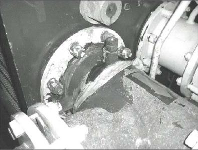 Figure 6. Erosion and galvanic damage behind the welding end at the UNS C70600 outlet pipe of a titanium heat exchanger operated at 4.2 m/s. The pipe and the heat exchanger were not electrically insulated.
The mechanism of erosion-corrosion is affected by hydrodynamic characteristics of the flow depending on the thickness of both the velocity boundary layer and the diffusion boundary layer at similar average flow velocities. As a result, the increasing boundary layer causes a decreased concentration gradient and thus reduces the mass transport. Consequently, if the corrosion process is determined by the mass transport from or to the surface, it can be expected that an increasing pipe diameter results in lowering erosion-corrosion rates and an increased breakdown velocity. Efird23 estimated that the critical velocity was 4.4 m/s for a tube 0.03 m in diameter and 6 m/s for a tube 3 m in diameter at 27°C. The calculated critical shear stress was 43.1 N/m2 for UNS C70600 in seawater indicating the conditions, under which the passive film is formed, must be considered.
Severe conditions might be expected if the pipe opening has a foreign body lodged in it causing throttling of the flow and leading to an abnormal increase in local flow velocity.21 Therefore, entrance of debris has to be prevented by installation of strainers. Also growth of macrofouling accumulations must be prevented by appropriate biocide treatment.
Campbell24 evaluated the effect of controlled bubble size (1.0 and 2.3 mm) on erosion-corrosion resistance and compared these results with bubble free water using a jet impingement apparatus. The deleterious effect decreases with smaller bubble size. To minimize this effect of gas bubbles, consideration should be given to the position of inlet boxes and the construction of venting systems.
It appears reasonable to suppose that an occasional reduction in velocity may contribute to repassivation and thickening of the surface film.25 Knutsson26 presented results of an examination of flow regimes over 12 months using a copper alloy. From 1 to 25 % flow duration, no attack was observed at 11.9 m/s. Continuous flow produced results of <15 µm/yr. at 6.1 m/s and 76 µm/yr. at 11.9 m/s. Therefore, for emergency situations, as in fire fighting systems which do not experience frequent pumping activity, the flow velocities up to 10-15 m/s are reasonable for UNS C70600. During two years of testing with sand loaded natural seawater by means of a once-through loop including pipes from 4" to 7" operated intermittently, no appreciable corrosion attack was detected at velocities up to 7 m/s.27
Negative effects of erosion are preventable by good design which is also necessary to improve the efficiency of the piping system. The general guidelines for reduction of friction loss depend on the flow velocity, pressure drop in the system due to the geometry of bends and valves, the required pumping power, and the probability of erosion-corrosion:
- The layout of the system should be as direct as possible.
- Control the flow with the least number of valves.
- Ask the valve manufacturer for data related to the effect of valve geometry on the pressure drop in the system. In most instances, there are considerable variations for nominally similar valves.
- Consider the effect of r/d-ratio of elbows and the effect of sudden enlargement and contractions on the pressure drop.
- When fittings are used, specify long radius and full-form types.
- Cut the gasket flush with the inner surface of the pipe.
- Provide a minimum distance of 5 x I.D. between a pump or a valve and a bend.
The exact adjustment of pipe ends and outlet is important to avoid protrusions that can lead to erosion damage in service. In all cases, 100 % weld penetration without excessive penetration of the root into the tube cavity is required to avoid causing any turbulence of the fluid in service. Mismatching of pipe ends should not exceed half of the wall thickness; however, it should be less than 2 mm.28
Effect of Chlorination
Chlorination of seawater is the most common method to control biofouling and it has been reported that continuous chlorination to a residual free chlorine level of 0.25 ppm can be 100 % effective against fouling. 29
It has also been reported that, in the presence of 0.25 ppm free chlorine, the corrosion of CuNi 90/10 increased during 30 days of exposure but the effect of the chlorine weakened subsequently.30 Kirk and co-worker16 stated that according to general experience no negative effect of chlorine concentrations 0.2-0.5 ppm was indicated on the corrosion behavior of copper-nickel alloy during many years in coastal power and process industries. In spite of the biofouling resistance of copper-nickel, the chlorine treatment extended the intervals between mechanical cleanings to restore the performance of heat exchangers from 2 months without chlorination to up to 1 year under chlorinated conditions in coastal plants.
Francis31, 32 published the results of tests related to the effect of chlorine additions in the range between 0.3 and 4.0 ppm on corrosion and jet impingement tests (jet velocity 9 m/s for 2 months) of UNS C70600 exposed to natural seawater. The products formed on cupronickel during chlorination led to appreciable anodic and cathodic polarization, and, thus, somehow to an improvement in corrosion resistance. Nevertheless, these products impaired the mechanical resistance of the copper-nickel surface leading to an increase in impingement susceptibility. For continuous and intermittent chlorine additions, the concentrations of 0.3 and 0.5 ppm respectively were recommended. Finally, the author pointed out that his results require more additional research.
Another study33 proposed a possible mechanism for the effect of free chlorine on corrosion performance of CuNi 90/10 in highly polluted brackish water containing appreciable amounts of planktonic and sessile sulfate reducing bacteria. It was assumed that the corrosion process in the presence of chlorine was controlled by transformation of Cu2O layer into secondary compounds such Cu2(OH)3Cl due to the high oxidizing power of the medium. These secondary products are not well adherent to the surface and easily removed allowing further Cu2O formation. Unfortunately, no mass loss or depths of corrosion attack were presented in this paper.
Obviously, more research is needed on the effect of chlorination on CuNi90/10. However, it can be concluded that an over-chlorination of seawater should be avoided.
Galvanic Corrosion
The avoidance of galvanic corrosion is a principal design consideration (Figure 7). Stainless steels undergo significant potential variations depending of chlorine and oxygen content, temperature, as well as presence of a biofilm, e.g. up to +800 mV SCE in seawater containing 0.5-1.0 ppm free chlorine to less than -400 mV SCE in deaerated seawater. In contrast, UNS C70600 reveals only small changes (Figure 8). It has been reported that the corrosion potential of this alloy remains in the range between 0 and - 300 mV SCE in natural aerated seawater at 10 and 40°C, in seawater flowing at 3 to 15 m/s at same temperatures, and in seawater containing 0.5 ppm free chlorine at 15°C. Figure 934 demonstrates the galvanic series of different commercial alloys in flowing seawater. UNS C70600 has a central position in the series. It is nobler than aluminum alloys, carbon and galvanized steel and less noble than stainless steels and titanium alloys. It can be coupled to tin and aluminum bronze.22
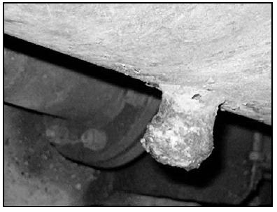 Figure 7. Galvanic corrosion damage of a carbon steel welding end welded directly to UNS C70600-pipe work.
 Figure 8. Typical values of corrosion potential for UNS C70600 under different seawater conditions. The potential axis represents the potential range of a super stainless steel.
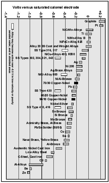 Figure 9. Galvanic series in flowing seawater at 2.5-4.0 m/s, 10-27°C.34
Bardal et al35 studied coupling of CuNi 90/10 with high-alloy stainless steel in natural and chlorinated seawater. During connection of the metals in chlorinated water, no significant effect of galvanic corrosion was found. The difference was attributed to the establishment of biofilm on high-alloy stainless steel in natural seawater providing a much higher cathodic efficiency. However, precautionary measures should be taken if the chlorination might be turned off.
For prevention of galvanic corrosion, it is recommended to use compatible materials wherever possible. However, in multi-material systems, the combination of different metals is often unavoidable. Thus the electrical contact of UNS C70600 with aluminum, nickel and titanium alloys, carbon and stainless steels should be avoided by application of commonly applied protection measures.
Stress-Corrosion Cracking
It has been reported36 that cupronickel failures due to stress-corrosion cracking are unknown in seawater polluted with ammonia. The alloys are also immune to chloride and sulfide stress corrosion cracking. Thus, no stress relief treatment is required for cold worked or welded material.
Conclusions
The merits of the UNS C70600 as an appropriate alloy for seawater pipework can be attributed to various aspects. First of all, it is a simple alloying system with a single phase face centered cubic structure providing excellent hot and cold workability. The absence of phase transformations during welding contributes to its easy weldability with no need for extensive post-weld treatments. However, the chemical composition and the manufacturing of cupronickel products must comply with international standards.
The low uniform corrosion rates of the alloy allow the specification of thinner walled piping and, therefore, provide weight saving. Cathodic protection is not usual for UNS C70600 piping. The alloy is resistant to biofouling and does not reveal sensitive corrosion potential variations under different seawater conditions. Such a combination of features leads to the improved resistance to localized corrosion and the elimination of extensive monitoring procedures associated with chlorination and higher seawater temperatures which other alloy systems might require. The alloy has high resistance to crevice corrosion and is resistant to stress corrosion cracking under marine conditions.
For lower seawater temperatures, protective surface films may take up to 3 months to fully mature. For this reason, hydrotesting and commissioning recommendations have been given. In addition, to avoid premature failures in the presence of hydrogen sulfide, precautionary measures are needed. The given practical recommendations should be followed to avoid corrosion problems. The susceptibility to erosion corrosion and galvanic corrosion can be eliminated by recommended design considerations.
References
- M. Hansen, and K. Anderko: Constitution of Binary Alloys, Second Edition, New York: McGraw-Hill Book Company Inc. 1958
- EEMUA No. 146 - 1987: 90/10 Copper Nickel Alloy Piping for Offshore Applications, Fittings
- M.S. Parvizi et al, International Materials Reviews, Vol. 33 No. 4 (1988), 169
- German Standard, WL 2.1972: 1996-08
- A Tuthill, Guidelines for the Use of Copper Alloys in Seawater, NiDI Publication 12003. 1988
- K.D.Efird, Materials Performance, November 1975, 37
- F.J Kievits and F.P. Ijsseling, Werkstoffe und Korrosion, 23 No. 12 (1972) 1084
- Tuthill et al., Experience with Copper Nickel Alloy Tubing, Water Boxes and Piping in MSM Desalination Plants, IDA World Congress on Desalination and Water Reuse, Paper No 73 Vol. III, p 251, Madrid, October 1977
- R.E. Melchers, Corrosion, Vol. 57 No. 5 (2001) 440
- K.D. Efird and T.S. Lee, Corrosion, Vol. 35 Feb. 1979, 79-83
- W. Schleich, and K. Steinkamp, Stainless Steel Conference 2003, Paper No: P0379, Maastricht
- Report, University of Applied Science Hamburg, No. K241-2000, Hamburg, July, 2000
- M.S., Parvizi et al., International Materials Reviews, Vol. 33 No. 4 (1988), 169
- B.C Syrett et al., Corrosion, 35 No. 9 (1979) 409
- L.E. Eiselstein et al., Corros. Sci., 23 No. 3 (1983) 223
- W. W. Kirk and A.H. Tuthill, Copper-Nickel Condenser and Heat Exchanger Systems, Paper from a Seminar, The Application of Copper-Nickel Alloys in Marine Systems, Presented Jointly by ICA, CDA and Nickel Development Institute in Cooperation with Japan Copper Development Association, Korean Institute of Metals, Tokyo, Osaka and Nagasaki, Japan, Pusan and Kirje Island, Republic of South Korea, November, 1991
- R. North and M.J. Pryor, Corrosion Science, 8 (1968) 149
- R. Gasparini et al., Corrosion Science, 10 (1970) 157
- S. Sato, Reviews on Coatings and Corrosion, (1973) 139
- C. A Powell and. H. T. Michels, Corrosion/2000, Paper No. 627, Orlando, Florida
- S. Sato and K. Nagata, Factors Affecting Corrosion and Fouling of Condenser Tubes of Copper Alloys and Titanium, Conference on Corrosion in the Power Industry, Montreal, 1977, NACE
- British standard: BSMA 18, Salt Water Piping Systems in Ships, August 1973,
- K.D. Efird, Corrosion, 33 No. 1 (1977) 3
- H.S Campbell and V.E. Carter, Journal of Inst. Metals, 90 (1961-62) 362
- B.C. Syrett: Corrosion, 32 (1976) 242
- L. Knutsson et al, Brit. Corros. J., 7 (1972) 208
- M. Jasner and K. Steinkamp, Why Copper Nickel 90/10 is the Optimum Pipe Material for Seawater Service, Stainless Steel World 2002, Houston, USA
- German standard: DIN 85004:1996-06
- D.B. Anderson and B.R Richards, Transaction of ASME, J. Eng. Power, July (1966), 203-208
- R.O. Lewis, Mater. Perfom, 22 (8), (1981), 31
- R. Francis, Materials Performance, August, 21 No. 8 (1982) 44
- R. Francis, Corrosion, 26 No.3 (1985) 205
- M. De Romero et al., Corrosion, 56 (8), 2000), 867-876
- Preventing Biofouling with Copper-Nickel, CDA Publication P157, Oct. 2002
- E. Bardal et al., Corrosion 40 (1984) 12
- P.T. Gilbert,: Br. Corrosion J. 14, 1 (1979), 20
- H. P. Hack and J. P. Gudas, Materials Performance, April (1980) 49
- H. P. Hack and T. S. Lee, The Effect of Ferrous Sulfate on Sulfide-Induced Corrosion of Copper-Base Condenser Alloys in Aerated Seawater, Report No. DTNSRDC/SME-81-91,David W. Taylor Naval Ship Research and Development Center, Maryland, January 1982
- M. W. Joseph and F. W. Hammond, Effect of Mechanical Cleaning for Heat Transfer Control on Corrosion of CuNi in Seawater Containing Sulfide and Ferrous Sulfate, Annual Report, INCRA Project No. 349B, February 1986
- H. P. Hack and J. P. Gudas, Inhibition of Sulfide-Induced Corrosion on Copper-Nickel Alloys with Ferrous Sulfate, Corrosion/78, Paper No. 23, NACE; Houston