by Carol A. Powell, Consultant to Nickel Development Institute; CDA Inc. Seminar Technical Report 7044-1919; 1992; Original title: The Application of Copper Nickel Alloys in Marine Systems.
- Introduction
- Corrosion Resistance
- Protective Film Formation
- Effect of Velocity
- Effect of Sulphides
- Effects of Seawater Treatments
- Biofouling
- Conclusions
- References
Introduction
The attractive corrosion and biofouling resistance of Cu-Ni alloys in sea water and related environments have led to their substantial use in marine service for many years. This introduction, will review the properties of the more commonly encountered alloys, while subsequent papers will detail some of their applications.
Historical
The two main, wrought Cu-Ni alloys chosen for sea water service contain 10 or 30 percent nickel, respectively. Both have important additions of iron and manganese which are necessary to maintain good corrosion resistance. Their development was based upon the understanding of how these additions, particularly iron, influence the alloys’ properties.
Development work began in the 1930s in response to a requirement by the British Navy for an improved condenser material. The 70-30 brass used at that time could not adequately withstand prevailing sea water velocities. Based on observations that the properties of 70-30 Cu-Ni tended to vary with iron and manganese levels, a composition was sought to optimize resistance to velocity effects, deposit attack and pitting corrosion. Typical levels of 0.6% iron and 1.0% manganese were finally chosen.(1)
Once successful service experience was achieved, interest was transferred to lower nickel compositions, initially as a replacement for copper sea water pipe work in naval applications. The 10% nickel alloy was eventually chosen, although in this case the optimum composition was identified to have a higher iron content and lower manganese level than the 70-30 alloy at typically 1.5% and 0.8%, respectively.
Since the 1950s, the 90-10 alloy has become accepted for condenser service as well as for sea water pipe work in merchant and naval service. In naval vessels, the 90-10 Cu-Ni is preferred for surface ships; whereas, the 70-30 alloy is used for submarines because its greater strength makes it more acceptable for the higher pressures encountered. These alloys are also used for power station condensers and offshore seawater pipe work on oil/gas platforms. Large quantities are selected for the desalination industry and they are additionally used for cladding and sheathing of marine structures and hulls.
Composition
When comparing international specifications, the compositional ranges of the two alloys vary slightly from specification to specification as can be seen in Table1. In practice, these variations have little influence on the overall service performance of the alloys.
Part 1. 90-10 | Part 2. 70-30 (below)
| ISO | BS | ASTM | DIN | |
|---|---|---|---|---|
| CuNi10FelMn | CN 102 | C70600 | CuNi10Fe 2.0872 |
|
| Copper min max |
Rem |
Rem |
Rem |
Rem |
| Nickel min max |
9.0 11.0 |
10.0 11.0 |
9.0 11.0 |
9.0 11.0 |
| Iron min max |
1.2 2.0 |
1.0 2.0 |
1.0 1.8 |
1.0 1.8 |
| Manganese min max |
0.5 1.0 |
0.5 1.0 |
- 1.0 |
0.5 1.0 |
| Tin min max |
- 0.02 |
- - |
- - |
- - |
| Carbon | 0.05 | 0.05 | 0.05* | 0.05 |
| Lead | 0.03 | 0.01 | 0.02* | 0.03 |
| Phosphorus | - | - | 0.02* | - |
| Sulphur | 0.05 | 0.05 | 0.02* | 0.05 |
| Zinc | 0.5 | 0.5 | 0.5* | 0.5 |
| Total other impurities |
0.1 | - | - | 0.1 |
| Total impurities | - | 0.3 | - | - |
| ISO | BS | ASTM | DIN | |
| CuNi30MnlFe | CN 107 | C71500 | CuNi30Fe 2.0882 |
|
| Copper min max |
Rem |
Rem |
Rem |
Rem |
| Nickel min max |
29.0 32.0 |
30.0 32.0 |
29.0 33.0 |
30.0 32.0 |
| Iron min max |
0.4 1.0 |
0.4 1.0 |
0.4 1.0 |
0.4 1.0 |
| Manganese min max |
0.5 1.5 |
0.5 1.5 |
- 1.0 |
0.5 1.5 |
| Tin min max |
- 0.02 |
- - |
- - |
- - |
| Carbon | 0.06 | 0.06 | 0.05* | 0.06 |
| Lead | 0.03 | 0.01 | 0.02* | 0.03 |
| Phosphorus | - | - | 0.02* | - |
| Sulphur | 0.06 | 0.08 | 0.02* | 0.05 |
| Zinc | 0.5 | - | 0.5* | 0.5 |
| Total other impurities |
0.1 | - | - | 0.1 |
| Total impurities | - | 0.3 | - | - |
| * When required for welding | ||||
Iron is essential for both alloys because it provides added resistance to corrosion caused by velocity effects called impingement attack. Figure 1 shows the effect of iron content on the impingement attack on 90-10 Cu-Ni from 30-day tests obtained at 3 m/s water velocity.(2) This is taken from the data compiled by various authors and different test facilities. A distinct minimum is apparent between 1.5 and 2.5% iron. Optimum iron levels are a result of solid solubility. The corrosion resistance improves with increasing iron so long as it remains in solid solution. The specification limits for alloys were set by this observation.
Figure 1. Effect on iron content on impingement attack on 90-10 Cu-Ni in seawater; all data from 30 day tests, curve is best fit for data obtained at 3 m/s.(2)
'
Figure 2. Corrosion resistance of Cu-Ni alloys as a function of iron content
Other properties also require consideration, and Figure 2 shows a schematic presentation by Gilbert(3) and of the iron compositional balance sought in the 90-10 and 70-30 alloys to optimize impingement resistance and resistance to various forms of localized corrosion.
Manganese is necessary as a deoxidant during the melting process, but its effect on corrosion resistance is less well defined than iron's. At lower levels of iron content, however, higher manganese levels lead to improved impingement properties.
Impurity levels must be tightly controlled because elements such as lead, sulphur, carbon and phosphorus, while having minimal effect on corrosion resistance, can influence hot ductility and, therefore, influence weldability and hot workability. Reputable suppliers are aware of this and endeavor to manufacture material with restricted impurity levels well within the specifications.
Mechanical Properties
Typical annealed mechanical properties for the two Cu-Ni alloys are shown in Table 2. Both alloys have good mechanical strengths and ductilities, although the higher nickel alloy does possess the greater inherent strength. Both alloys are single phase, solid solution alloys and cannot be hardened by heat treatment. The strengths, however, can be increased by work hardening. Whereas, 90-10 copper nickel tubing can have a proof stress of 100-160 N/mm2 when supplied in the annealed condition, this could typically be 345-485 N/mm2 in the as-drawn condition.
| Property | 90-10 | 70-30 |
|---|---|---|
| Proof Stress N/mm2 | 140 | 170 |
| Tensile Strength N/mm2 | 320 | 420 |
| Elongation % | 40 | 42 |
Physical Properties
A comparison of the physical properties of the two alloys are given in Table 3.(4) Of particular interest for heat exchangers and condensers are the thermal conductivity and expansion characteristics. Although conductivity values for both are good, the 90-10 alloy has the higher value. This partly explains the alloy's greater popularity for heat exchanger and condenser service, where higher strength is not the most important factor.
| Property | 90-10 | 70-30 |
|---|---|---|
| Specific Gravity (g/cm3) | 8.9 | 8.95 |
| Specific Heat (J/kg K) | 377 | 377 |
| Melting Range (°C) | 1100 - 1145 | 1170 - 1240 |
| Thermal conductivity (W/mK) | 50 | 29 |
Coefficient of linear expansion
|
13 17 |
12 16 |
| Electrical Resistivity (microhm cm) | 19 | 34 |
| Coefficient of electrical resistivity (10-6) | 70 | 50 |
Modulus of Elasticity (GN/m2)
|
135 127 |
152 143 |
Modulus of Rigidity (GN/m2)
|
50 47 |
56 53 |
The 70-30 alloy is essentially nonmagnetic and has a magnetic permeability very close to unity. The 90-10 alloy with higher iron content is nonmagnetic, if the iron can be retained in solid solution during processing. For 90-10 tubing used in minesweepers, air cooling after the final anneal suppresses precipitation sufficiently to provide low permeability.
Corrosion Resistance
Metals and alloys are subject to several forms of corrosion in sea water including general wastage, impingement attack and localized corrosion, such as pitting, crevice corrosion, stress corrosion cracking and intergranular attack. The continued use of Cu-Ni in sea water has confirmed its good resistance to the wide range of corrosion mechanisms.
General Corrosion
General corrosion rates for 90-10 and 70-30 Cu-Ni alloys in sea water are low, ranging between 0.025 and 0.0025 mm/yr(5) For the majority of applications, these rates would allow the alloys to last the required lifetime, and there would be little probability of their premature failure in service due to such a corrosion mechanism.
Fourteen years of data collected at the LaQue Center for Corrosion Technology at Wrightsville Beach, North Carolina, USA, for 90-10 and 70-30 alloys (6) in quiet, flowing (0.6 m/s) and tidal conditions are shown in Figure 3 and Figure 4. It was found that, in all instances, corrosion rates were higher during early stages of testing, before stabilizing at lower values. The highest initial corrosion rates were found in flowing sea water; although in the latter years of testing, the corrosion rates for 90-10 were similar in all the conditions. For 70-30 Cu-Ni, this was true for quiet as well as flowing conditions, but corrosion rates were consistently lower for tidal conditions throughout. Both alloys show low general corrosion rates, with the 70-30 alloy having slightly better overall levels.
Figure 3. The change in corrosion rate with time for 90-10 Cu-Ni in quiet, flowing, and tidal zone seawater
Figure 4. The change in corrosion rate with time for 70-30 Cu-Ni in quiet, flowing, and tidal seawater
Pitting and Crevice Corrosion
Alloys protected by a passive film, such as stainless steels, tend to have low general corrosion rates but can suffer localized corrosion once the film is damaged. This occurs in susceptible alloys, particularly at velocities of less than l m/s when marine fouling attachments can form additional crevice sites. At higher velocities, marine organisms have difficulty becoming attached.
Although Cu-Nis have a passive surface film, they have advantages over some other alloy types by having a high resistance to biofouling, thereby decreasing the number of potential sites where corrosion could occur. The Cu-Nis also have a high inherent resistance to pitting and crevice corrosion in quiet sea water. Pitting penetration rates can conservatively be expected to be well below 0.127 mm/year Sixteen-year tests(7) on 70-30 alloy reported the average depth of the twenty deepest pits to be less than 0.127 mm. When pits do occur, they tend to be shallow and broad in nature and not the undercut type of pitting which can be expected in some other types of alloys.
Crevice corrosion seldom occurs in Cu-Ni alloys and little data is published about the phenomenon.(2) When encountered, it tends to be metal ion concentration cell corrosion C the opposite of that occurring in stainless steels, for example. Metal ions accumulate in the crevice area and the crevice becomes noble. Dissolution occurs adjacent to the crevice on surfaces exposed to oxygenated bulk sea water. Water velocity can aggravate this type of attack, although penetration rates are unlikely to be severe.
Stress Corrosion Cracking
The 90-10 and 70-30 Cu-Nis are resistant to chloride and sulphide stress corrosion cracking.
Some copper-based alloys such as aluminum brass are subject to stress corrosion cracking in the presence of ammonia. In practice, this prevents their use in the air-removal section of power plant condensers. Cu-Ni alloys, however, are resistant to stress corrosion cracking and are commonly used in air-removal sections.
Galvanic Effects
Cu-Ni alloys are fairly central in the galvanic series. They are: less noble than titanium, nickel-copper alloys and stainless steels; compatible with other copper-based alloys; and more noble than steels. The 70-30 alloy is slightly more noble than the 90-10 alloy but not significantly so. The two alloys, therefore, can successfully be coupled.
Weld Areas and Denickelification
The corrosion resistance of weld deposits made by approved weld consumables and of the adjacent, heat affected zone in these alloys does not pose a problem, as may be the case in some other alloy systems. The 90-10 alloy is normally welded with a 70-30 Cu-Ni consumable and provides a weld which is galvanically slightly more noble than the base metal. Nickel-copper (65Ni-35Cu) consumables are used for Cu-Ni to steel welds.
Denickelification in the 70-30 alloy has been encountered occasionally in refinery overhead condenser service, where hydrocarbon streams condense at temperatures above 150°C. This appears to be due to thermogalvanic effects resulting from the occurrence of local hot spots The solution has been to remove deposits which lead to the hot spots, either by more frequent cleaning or by increasing flow rates.
Protective Film Formation
The good corrosion resistance in sea water offered by Cu-Ni alloys results from the formation of a protective oxide film on the metal surface. The film forms naturally and quickly changing the alloys' initial exposure to sea water.
In clean sea water, the film is predominantly cuprous oxide, with the protective value enhanced by the presence of nickel and iron. Cuprous hydroxy-chloride and cupric oxide are often also present.(7),(8)
The film can be brown, greenish-brown or brownish-black. In 90-100 Cu-Ni, the film thickness can be in the order of 4,400 A.(2),(8)
The rate of film formation was portrayed by Tuthill (8) from measurements of the copper content of condenser sea water effluent over a 3-month period after start up, Figure 5. Copper content was found to decrease to 1/10 in 10 minutes and to 1/100 in an hour. After 3 months, the copper in the effluent was at virtually the same level as that in the intake water. This indirectly shows that the maturity of the protective film reduced the corrosion rate of the condenser tube surfaces.
 Figure 5. Formation rate of corrosion film on 90-10 Cu-Ni in seawater (8)
The film, however, continues to become even more protective with time, as indicated by corrosion rate measures made over several years. Studies in quiet sea water show that the timespan approaches 4 years before the decrease in corrosion rate becomes negligible. In flowing water, the corrosion rate, as shown in Figure 3 and Figure 4, was found to decrease continually over at least a 14-year period, the effect being similar for both 90-10 and 70-30 alloys.
The composition and properties of the film depend on the alloy composition and the condition of sea water at the time of initial exposure. In polluted sea water, any sulphides present can interfere with film formation, producing a black film containing cuprous oxide and sulphide.(2) This film is not as protective and adherent as films formed in unpolluted water. However, if an established cuprous oxide film is present, then periodic exposure to polluted water can be tolerated without damage to the film.
Effect of Velocity
The combination of low general corrosion rates and high resistance to pitting and crevice corrosion ensures that the Cu-Ni alloys will perform well in quiet, clean sea water. As the flow rate of sea water increases, the corrosion rate remains low due to the protective surface film on the alloys. However, once the velocity is such that the film becomes damaged and the active underlying metal is exposed, erosion corrosion (impingement attack) will occur rapidly. The sea water velocity at which this occurs is often called the "breakaway velocity" and different copper-based alloys show different breakaway velocities.
Figure 6, prepared by Gilbert,(3) can be used to illustrate the relative velocity limitations for various copper-based alloys. The 90-10 Cu-Ni has better impingement resistance than aluminum brass, which in turn is better than copper. The 70-30 alloy shows better resistance than the 90-10 alloy.
 Figure 6. Velocity limitations for copper alloys in seawater
This is not a complete representation, however. Rates of attack are not only dependent on sea water velocity but also on pipe work diameter.
Many studies have evaluated the impingement resistance for marine condensers and piping involving several types of test apparatus, including rotating discs, rotating spindles, model condensers, multi-velocity jet tests and jet impingement tests. These trials have proved reliable in ranking materials as a function of impingement resistance, but results vary from one test apparatus and laboratory to another.
Table 4, below, compares results of tests on condenser tube alloys using the jet impingement technique in two laboratories; one in the UK and the second in the USA. These tests involve a jet of sea water containing 3% air, projected at about 5 m/s against a metal surface and then taking measurements of the depth of attack. Alloys with high resistance to impingement attack, such as iron-containing Cu-Ni, show less penetration in this test than alloys of lower resistance. However, in this work it is notable that once-through natural sea water at the USA laboratory caused greater attack in general than the recirculated water used in the UK trials.(9) Note, too, the beneficial effect of the high iron content in the 70-30 Cu-Ni alloy.
| Material | Average depth of attack (mm) | |
|---|---|---|
| BNFMA | LCCT | |
| Aresenical Admiralty Brass | 0.34 | 0.27 |
| Aresenical Copper | 0.30 | - |
| 70-30 Cu-Ni, 0.04% Fe | 0.11 | 0.22 |
| Aluminum Brass | 0.04** | 0.2 |
| 70-30 Cu-Ni, 0.8% Fe | 0.02 | - |
| 70-30 Cu-Ni 0.45% Fe | - | 0.1 |
| 90-30 Cu-Ni, 2% Fe | 0.00 | 0.15 |
| * Also known as BNF-Fulmer ** One specimen out of 20 pitted to a depth of 0.65 mm. No other specimen greater than 0.2mm. |
||
General experience has shown that 90-10 Cu-Ni can successfully be used in condensers and heat exchangers with water velocities up to 2.5 m/s. For pipeline systems, higher sea water velocities can safely be used in larger diameter pipes as indicated by codes of practice. BS MA 18, "Salt Water Piping Systems in Ships," for example, suggests a maximum velocity of 3.5 m/s in pipes of 100 mm diameter and larger, decreasing to 0.7 m/s in pipes of 10 mm diameter or smaller. For 70-30 Cu-Ni, the maximum design velocity is given as 4 m/s for diameters of 100 mm or greater.
In practice, such guidelines have worked well because they take into account normal velocity raisers within pipe work systems, such as bends, etc., which can cause areas of higher flow rate.
Nevertheless, extreme turbulence has to be avoided. Instances where this may occur include tight radius bends, partial blockages and areas downstream of partially-throttled valves.
One theory, based on work carried out by Efird(11) is that sea water moving over a surface creates a shear stress between the metal surface and the layer of sea water closest to it. As velocity increases, shear stress increases until the stress is such that it damages the protective film.
Efird studied and estimated the critical shear stress for various alloys. Shear stresses exerted vary with velocity and geometry as indicated by Figure 7. As pipe diameters increase, copper-based alloys tolerate higher nominal velocities.
 Figure 7. Variation in shear stress between in flowing seawater and metal wall with the nominal velocity in the pipe and diameter of the pipe (11)
Sato and Nagata(10) also showed that the shear stress at the inlet end of a condenser tube is double that found farther down, Figure 8. This indicates why copper-based alloys with higher resistance to impingement, such as the Cu-Nis, are necessary to withstand corrosion problems in such areas.
 Figure 8. Variation of shear stress between the flowing seawater and metal wall with the distance
from the inlet end.(10)
Four-month tests by Kirk(12) using 102 mm ID, 90-10 Cu-Ni, straight pipe work and long radius bends showed good resistance to a 7.3 m/s sea water flow velocity. This indicated that safe velocities may be higher than the 3.5 m/s maximum level often used in large-diameter pipe work, particularly when protective films are formed in clean, aerated sea water.
Although 90-10 Cu-Ni pipe work may be limited to 3.5 m/s, the shear stress phenomenon helps explain why the alloy has been successfully used for ship hulls operating at 24 knots (12 m/s) with little thinning experienced. More work is necessary to explain the full extent of hydrodynamics on a flow system.
Other Cu-Ni alloys have been developed and found to offer even better resistance to impingement attack. In particular, a 16.5%Ni-0.5% Cr alloy developed by INCO in the 1970s has a much higher, critical shear stress than the 70-30 alloy and is used for condenser and heat exchanger service. Also a 2%Mn-2%Fe, 70-30 Cu-Ni alloy, developed for extra impingement resistance in situations where entrained sand is present in sea water, is now successfully used in the more demanding areas of desalination plants.
Effect of Sulphides
Sulphides are present in polluted water either as industrial effluent or when water conditions support the growth of sulphate reducing bacteria. They can also occur in stagnant sea water by decomposition of organic matter to sulphides and ammonia.
Sulphides form a black corrosion product which is less adherent and protective than the normal oxide film. Under susceptible conditions, unwanted pitting or accelerated general corrosion may occur.
In the complete absence of oxygen, a sulphide film can show an acceptable degree of protection. Syrett found that corrosion rates still remain low in sulphide concentrations as high as 55 g/m3 and velocities up to 5 m/s.(8) However, the sulphides become detrimental if dissolved oxygen is also present in the sea water, or if exposure to oxygen-free sulphide polluted waters is followed by exposure to aerated, unpolluted waters.
The presence of as little as 0.01 mg/1 of sulphides has been shown to accelerate attack of 90-10 Cu-Ni in aerated sea water, although the combined influence of velocity and sulphides makes the effect more significant. Figure 9 and Figure 10 illustrate this for 90-10 and 70-30 Cu-Nis.(7)
Figure 9. Corrosion rates for 90-10 copper nickel as a function for seawater velocity and sulphide content
Figure 10. Corrosion rate for 70-30 Cu-Ni as a function of seawater velocity and sulphide content
Various explanations exist to describe how the corrosive influence of sulphides can be linked to the surface film. One explanation is that the sulphide film has been found by potential measurements to be galvanically more noble than the normal film. It is less adherent, and when damaged by impingement, the more active base metal is exposed and the corrosion rate is galvanically influenced.
Whatever the reasoning, the sulphide film which forms in polluted water will be replaced by a normal oxide film once the polluted sea water is replaced by clean, aerated sea water. This occurs when vessels are fitted out in polluted harbors and then operate in the open sea. Higher corrosion rates do continue for some time during the transition period. Syrett found that the transition can take nine days. Experience has shown that as soon as vessels begin regular operation, the normal protective film, once adequately formed, will also persist during subsequent harbor visits.
The ideal situation, whether in a ship or power plant, is to recirculate aerated, clean sea water at initial start up for sufficient time to form a good protective film. When formed, this provides a high degree of corrosion protection to subsequent exposure to sulphides.
In situations where it is not possible to use clean sea water, circulating the system initially with fresh water containing ferrous sulphate additive will encourage effective film formation.(13)
If polluted sea water is introduced at start up, it is important to keep the water circulating to enable aeration and to keep the pH at neutral or above. The system should be drained and air-blown dry for standby period of 3-4 days or more.
For situations where there is brief exposure to sulphides during normal operating service conditions, clean sea water should be returned as soon as possible. Normal harbor turnaround times, which often involve exposure to polluted water, have rarely led to significant corrosion problems.(7)
For other situations where the metal surface becomes exposed to sulphides under deposits or sediment caused by sulphate-reducing bacteria (e.g., where deposits are not removed from tubing), the remedy is simply properly scheduled cleaning. Such cleaning is usually scheduled at 2-6 month intervals and accomplished by water flushing or cleaning with nonmetallic brushes. This procedure is also necessary to restore optimum heat transfer.
Where there is long-term exposure to deaerated sulphide-containing sea water or regular (e.g., daily tide changes) alternating exposure to sulphide-polluted and aerated waters, Cu-Ni is not generally recommended.
The Effect of Seawater Treatments
Ferrous Sulphate
Ferrous ion additions are commonly used to reduce the corrosion of Cu-Ni alloys either by a direct addition of ferrous sulphate or by means of a driven iron anode.
Ferrous ions in seawater are very unstable and can decay within as little as three minutes (2) Therefore, the treatment is more effective when additions are continuous rather than intermediate. Ferrous ion treatment has been found to suppress the corrosion rates of Cu-Ni in both polluted and unpolluted conditions. However, it is particularly attractive when supplies are present in the seawater. For example, to encourage good initial film formation during fitting out, a system can be filled initially with fresh water containing 5 ppm ferrous sulphate and left in the system for one day. After this, the system can be used for normal fitting out purposes, but the ferrous sulphate solution (5 ppm concentration) should be recirculated for 1 hour per day throughout the fitting out period.(13) This practice is also useful when systems are retubed or renewed.
During normal service on ships, additional ferrous sulphate dosing is seldom required. Although if exposure to known polluted water is going to occur (e.g., when entering port), a reasonable additional precaution would be to add 5 ppm ferrous sulphate for 1 hour per day during the 3 days prior to entering, while in, and after leaving port. One treatment per week can be applied throughout a prolonged voyage.
Ferrous sulphate is not essential to successful performance but can be viewed as a remedy when trouble has occurred or as a precaution if trouble is likely. Most ships in service have operated successfully without any ferrous sulphate dosing.
Chlorination
Chlorine is used as an effective biocide when injected continually so that 0.2 to 0.5 ppm residual is maintained at the outlet tube sheet of a power plant condenser.(8)
Cu-Ni tubing is resistant to chlorination at concentrations normally required to control biofouling. Excessive chlorination, however, can damage copper alloy tubing.
There is some evidence that at high velocities, chlorination has the effect of increasing the impingement rate in the 90-10 alloy; although in 70-30, the rate is decreased.(7) Figure 11 and Figure 12 illustrate this effect, showing plots of chlorine level verses impingement attack in 90-10 and 70-30, respectively. An impingement jet velocity of 9 m/s was used. It should be noted, however, that 9 m/s velocity is not normally encountered or recommended for Cu-Ni alloys.
Figure 11. Depth of impingement attack versus chloride level for 90-10 copper nickel in seawater
with an impingement jet velocity of 9 m/s
Figure 12. Depth of impingement attack versus chlorine level for 70-30 Cu-Ni with an impingement jet velocity of 9 m/s
Biofouling
Marine biofouling is commonplace in open waters, estuaries and rivers. It is commonly found on marine structures including pilings, offshore platforms, boat hulls and even within piping and condensers. The fouling is usually most widespread in warm conditions and in low velocity (<1m/s) sea water. Above l m/s, most fouling organisms have difficulty attaching themselves to surfaces unless already secured. There are various types of fouling organisms, particularly, plants (slime algae) sea mosses, sea anemones, barnacles and molluscs (oysters and mussels). In steel, polymers, and concrete marine construction, biofouling can be detrimental, resulting in unwanted excess drag on structures and marine craft in sea water or causing blockages in pipe systems. Expensive removal by mechanical means is often required. Alternatively, costly prevention methods are often employed, which include chlorination of pipe work systems or antifouling coatings on structures.
Marine organisms attach themselves to some metals and alloys more readily than they do to others. Steels, titanium and aluminum will foul readily. Copper-based alloys, including Cu-Ni, have very good resistance to biofouling, and this property is used to advantage. In the case of Cu-Ni, it is used to minimize biofouling on intake screens, sea water pipe work, water boxes, cladding of pilings and mesh cages in fish farming. A prime example of this was in 1987 when two early Cu-Ni hulled vessels, the Asperida II and the Copper Mariner, were located after being in service for 21 and 16 years, respectively. Neither vessel required hull cleaning or had suffered significant hull corrosion during that time.(14)
Efird, during the 14-year trials discussed earlier in the context of general corrosion rates in quiet, flowing and tidal conditions,(6) examined the final samples for biofouling. Both the 90-10 and 70-30 samples showed minimal fouling after removal from all three types of exposures, although different types of marine organisms appeared to adapt to different exposure conditions.
In quiet sea water, serpula, anomia, small barnacles and crisia bryozoa were found. For flowing sea water, barnacles, anomia and some serpia were observed, although they were of insignificant size. In the tidal zone, there were small serpulids and a few small barnacles, oysters and mussels.
During long-term exposure, therefore, some biofouling is possible. Another trial, again by Efird, examined more closely the progression of biofouling on immersed samples of 90-10 and 70-30 Cu-Ni over a five-year period.(15)
Plates, immersed from a floating dock at the LaQue Center for Corrosion Technology, showed very little fouling after 18 months, apart from slimes on both alloys. But after five years, fouling covered two thirds of the surfaces. The type of fouling was tunicates, bryozoa and serpulids. There was little to distinguish between the 90-10 and 70-30 alloys, Figure 13 and Figure 14.
 Figure 13. The five year sequence of fouling on 90-10 Cu-Ni (CA 706) in seawater.
 Figure 14. The five year sequence of fouling on 70-30 Cu-Ni (CA 715) in seawater.
It was noted in the Efird trials that, at various intervals during exposures, the fouling would become detached and then new fouling would attach itself. It should be noted, however, that these trails were carried out under relatively sheltered conditions where slime layers are allowed to thicken to a point where biofouling can become attached. With the wave action on offshore platforms or with the normal flow velocities in cooling systems, the slime layer would not reach a thickness on Cu-Ni to permit attachment.
Another study by Jackson at Langstone Harbour, (16) in the UK looked only at 90-10 Cu-Ni. This examined the exposure of four different test panels at two types of testing sites. The intention was to examine the biofouling behavior of cathodically-protected compared to freely corroding Cu-Ni for structural sheathing.
The four panels are depicted in Figure 15. From left to right, the figure shows a steel panel attached to an aluminum anode, a cathodically-protected composite panel of steel with Cu-Ni sheathing welded onto it, a Cu-Ni panel protected by an aluminum anode, and a freely-corroding Cu-Ni panel. A hole had been drilled in the composite panel with Cu-Ni sheathing to expose a small area of steel.
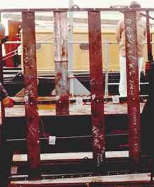 Figure 15. Raft site - mounted panels being lowered into place
One test rack was attached to a floating raft so that it would be immersed to the same depth of water, regardless of the tide. A second rack was attached to a sand bank and, therefore, was alternately immersed in sea water and then exposed to the atmosphere for 8-hour intervals every day. The raft trial lasted 137 weeks; the sand bank trial ceased after 378 weeks.
For the raft trial, it was found that slimes were formed on the steel before any of the Cu-Ni surfaces. But, by the end of the first fouling season, biofouling was evident on all cathodically protected panels. This was in the form of sea squirts, sponges and, later, from weed. The fouling, however, could be dislodged more easily from the cathodically protected Cu-Ni panel than from the steel.
The freely corroding panel developed a green, corrosion product film during the first weeks. There was minor attachment during successive fouling seasons, Figure 16, but these were lost during the following winter periods.
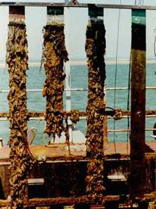
Figure 16. Raft site - Raft site - 55 weeks immersion

Figure 17. 90-10 Cu-Ni and 50D steel after 16 weeks on the half tide site.
There was no preferential corrosion of the steel on the composite panel adjacent to where the Cu-Ni was welded to the steel, and only superficial corrosion had occurred on the steel below the drilled hole.
This work shows how resistance to biofouling relies on the Cu-Ni being in the freely corroding state. With cathodic protection, biofouling will occur, although organisms do not appear to attach themselves as tightly to Cu-Ni as they would to steel.
On the half tide site, the pattern of fouling was different and took longer to develop. In the first few months calcareous deposits were formed on the cathodically protected Cu-Ni. Barnacles were the first to colonize. On the composite panel this was initially on the welds, Figure 17, which had been made with a 70-30 consumable, indicating that the higher-nickel alloy (in the early stages at least) was less biofouling resistant. By 55 weeks, Figure 18, some fouling in terms of barnacles and weed was evident on all panels, although the freely corroding panel had significantly less. The barnacles on the protected Cu-Ni were easily removed by a light rubbing with a finger.

Figure 18. 55 weeks on half tide site

Figure 19. Insulated 90-10 Cu-Ni after 378 weeks on half tide site
After 378 weeks, all protected panels were well covered, and some biofouling was evident on the freely corroding panel, Figure 19. The fouling could be more easily removed from all the Cu-Ni surfaces than from steel surfaces.
Like Efird, Jackson noted different types of biofouling after the different types of exposure. He also noticed signs of biofouling removal that went beyond the regular reduction found during the winter season, which was considered to be due to wave action.
Explanations for Biofouling Resistance
In the past, the need for copper and Cu-Ni to be freely corroding to exhibit biofouling resistance has led researchers to believe that it is the copper ion entering the sea water that is toxic to marine organisms. Efird argued from his studies that this was incorrect because 90-10 and 70-30 Cu-Nis corroded far more slowly than copper and still exhibited similar biofouling resistance over long-term exposures. He considered that it was the surface film, itself, which was inhospitable to biofouling. The toxic-ion-being-released-into-sea-water theory was further disputed by Efird based on tests he carried out on 90-10 samples half-coated with nontoxic paint, Figure 20, over a period of 24 weeks. If leaching of copper ions was the phenomenon, some protection of the nontoxic surface would be offered. Due to the distinct cut-off line after 7 weeks, this did not appear to be the case. By 24 weeks, fouling on the nontoxic surface had started to creep above the Cu-Ni which also, would not have been expected with the leaching theory.
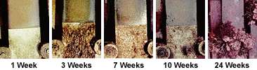
Figure 20. The influence of 90-10 Cu-Ni on the fouling of an adjacent non-toxic (vinyl paint) surface in seawater during summer fouling season.
Because it was found that, after extended time periods, the Cu-Ni alloys tend to alternately lose and gain their fouling resistance, Efird concluded that the film is duplex in nature. It was thought that the initial cuprous oxide film is resistant, but when it oxidizes after extended exposure to form a green cupric hydroxychloride, fouling seems to increase. Because the second film is not so adherent, it can be easily removed, preventing secure attachment. Once sloughed off, the exposed surface is resistant again.
Microfouling
Copper alloys have good resistance to microfouling, although they are not totally immune to it. Microfouling can be found in heat exchanger and condenser tubing. Figure 21(8) shows the reduction in heat transfer for 90-10 Cu-Ni that results from the growth of microfouling film on the inside wall in clean sea water at 1.8-2.4 m/s over 180 days. A 90 to 100 day interval between cleanings for copper alloys was indicated and it compared favorably with the 10-day interval found necessary for other alloy condenser tube in the study.
 Figure 21. Resistance of 90-10 Cu-Ni to heat transfer resulting from the growth of a
microfouling film on the inside wall of tube in clean seawater.
The ability of Cu-Ni to resist microfouling and remain effective as a heat transfer surface in sea water for the 3 to 4 month normal intervals between mechanical cleanings, without chlorination, is of clear benefit and one of the reasons why copper nickel continues as a useful tubing material wherever saline waters are used for cooling.
Conclusions
Both the biofouling and corrosion resistance properties of 90-10 and 70-30 copper nickels appear strongly linked to the nature of the protective film formation on the alloys' surfaces. From various observations and studies, this film is complex and variable, although its importance is never in dispute.
The passive surface is responsible for high resistance to general corrosion, pitting, crevice attack and stress corrosion cracking. Resistance to velocity effects encountered under normal system flow rates is also good, although excessive turbulence may damage the protective film.
The inhospitable nature of the surface film is additionally thought to be the reason for biofouling resistance in Cu-Ni alloys. To maintain this property, a freely corroding state is necessary.
References
- 90/10 and 70/30 Alloys Technical Data, Publication TN 31, , CDA UK, .
- Behaviour of 90-10 cupronickel in sea water, Parvizi, M. S., Aladjem, A., & Castle, J. E., International Materials Reviews, Vol. 33, 4, pp 169-200, , .
- Biofouling and Corrosion Testing at AMTE, Langstone Harbour, Jackson, K. T., , IMI Yorkshire Alloys Ltd., Unpublished report .
- Copper Nickel Alloys, Properties and Applications, TN 30, , Joint Publication of the Copper Development Association (UK) and the Nickel Development Institute, Joint Publication of the Copper Development Association (UK) and the Nickel Development Institute .
- Copper-Nickel Hulled Boats Around The World, From New York To Genoa, Are Free Of Fouling, , From Copper Topics, CDA Inc. .
- Copper Nickel Iron Alloys Resistant to Sea Water Corrosion, Bailey, G. L., Journal of the Institute of Metals, Vol. 79, pp 243-292, , .
- Corrosion and Marine Fouling Characteristics of Copper Nickel -Alloys, Kirk, W. W., T. S. Lee, and R. O. Lewis, Paper 16, , CDA Conference Copper in Marine Environments, .
- Corrosion Resisting Properties of 90/10 Copper-Nickel-Iron Alloys with Particular Reference to Offshore Oil and Gas Applications, Gilbert, P. T., British Corrosion Journal, Vol. 14, 1, pp 20-25, , Institute of Materials, .
- Effect of Fluid Dynamics on the Corrosion of Copper Base Alloys, Efird, K. D., Corrosion, Vol. 33, 1, pp 3-8, , .
- Evaluation of Critical Seawater Hydrodynamic Effects of Erosion-Corrosion of CuNi, Kirk, W. W., , ICA, Contractor Report Technology for the Copper Industry: Final Report INCRA Project No. 396 .
- Factors Affecting the Corrosion and Fouling of Metal Condenser Tubes of Copper Alloys and Titanium, Sumitomo Light Metal Technical Reports, Vol. 19, Nos. 3 and 4, , .
- Guidelines for the Use of Copper Alloys in Seawater, Tuthill, Arthur H., Materials Performance, Vol. 26, 9, pp 12-22, , CDA Inc Publication 788/8 and Nickel Institute Publication12003 .
- Jet Impingement Tests, Gilbert and LaQue, Journal of the Electrochemical Society, Vol. 101, No. 9, , .
- Sea water Corrosion Resistance of 70-10 and 70-30 Copper nickel-14 year Exposures, Efird, K. D. and D. B. Anderson, Materials Performance, Vol. 14, 11, pp 37-40, , .
- Selecting Materials for Sea Water Systems. Institute of Marine Engineers, Todd and Lovett, .
- The Interrelation of Corrosion and Fouling of Metals in Seawater, Efird, K. D., Materials Performance, Vol. 15, 4, pp 16-25, , .