Results
Microstructures
Microstructures of both Alloy A and Alloy B were examined and all phases were named in accord with the convention developed by Howell (10), which was based upon the work of Brezina (11). The phases formed as a result of heat treatment are listed in Table 4. As can be seen in Figure 2, Alloy A in the oil quenched (OQ) condition contained proeutectoid α, which precipitates as Widmanstatten rods within a continuous matrix of Martensite and Bainite. The Martensite and Bainite phases are typically found together in these alloys and are collectively termed α*. The mention of one does not imply that the other is not present. When air cooled (AC), Alloy A contains more Widmanstatten proeuetectoid α and less α * than the oil quenched (OQ) specimen , as can be seen by comparing Figures 2 and 3, and as listed in Table 4. In addition, small amounts of a eutectoid of α + κ III can also be seen on the outer edges of the proeutectoid α in the in Alloy A in the air cooled (AC) condition, as shown in Figure 3. In Alloy A, tempering facilitates the transformation of Martensite and Bainite or α *, to a fine eutectoid of α + κ III . The κ III phase is generally associated with tempering (10) and results in a more diffuse or as a less distinct microstructure,(10). The κ III structure is the based upon NiAl and its composition varies from NiAl to FeAl (10). The fine eutectoid, consisting α + κ III , as well as lesser amounts of α * and proeutectoid α can be seen in Figure 4 in the oil quenched and tempered (OQ+T) condition. Only the fine eutectoid, consisting α + κ III , can be seen in Figure 5 in the air cooled plus tempered (AC+T) condition, where remnants of proeutectoid α grain boundaries can also be faintly seen . Alloy A, when furnace cooled (FC), contains Widmanstatten proeutectoid α, the eutectoid of α + κ III at the edges of the proeutectoid α, as well as traces of isolated κ II within the α + κ III eutectoid, as shown in Figure 6. The structure of the small angular κ II phase is based upon Fe 3Al, and is frequently associated with high temperature and high Al Martensite or α + κ III eutectoid (10).
| Heat Treatment Code | Alloy A (9.4% Al) | Alloy B(8.1% Al) |
|---|---|---|
| OQ | ~30% Proeutectoid ( α) ~70% Martensite/Bainite ( α *) (see Figure 2) | ~60% Equiaxed Proeutectoid (α) ~40% Martensite/Bainite ( α *) (see Figure 7) |
| AC | ~70% Proeutectoid ( α) ~25%Martensite/Bainite ( α *) ~5% Eutectoid ( α + κ III) (see Figure 3) | ~60% Equiaxes Proeutectoid (α) ~40% Martensite/Bainite ( α *) (see Figure 8) |
| OQ+T | ~80% Eutectoid ( α + κ III) ~10% Proeutectoid ( α) ~10% Martensite/Bainite ( α *) (see Figure 4) | ~80% Equiaxes Proeutectoid (α) containing a fine planar precipitate ( κ III) ~20% Martensite/Bainite ( α *) (see Figure 9) |
| AC+ T | Eutectoid ( α + κ III) (see Figure 5) | ~80% Equiaxes Proeutectoid (α) containing a fine planar precipitate ( κ III) ~20% Martensite/Bainite ( α *) (see Figure 10) |
| FC | ~70% Proeutectoid (α) ~30% Eutectoid ( α+ κ III) traces of isolated ( κ II) (see Figure 6) | ~60% Equiaxes Proeutectoid (α) containing a very fine precipitate ( κ III) ~40% Eutectoid ( α + κ III) traces of isolated ( κ II) (see Figure 11) |
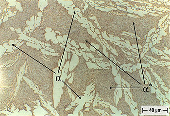 Figure 2. Alloy A (9.4% Al), Solution Annealed and Oil Quenched (OQ).
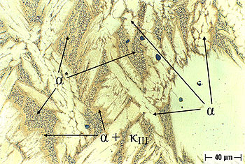 Figure 3. Alloy A (9.4% Al), Solution Annealed and Air Cooled (AC).
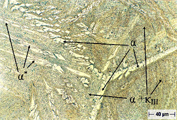 Figure 4. Alloy A (9.4% Al), Solution Annealed, plus Oil Quenched and Tempered (OQ+T).
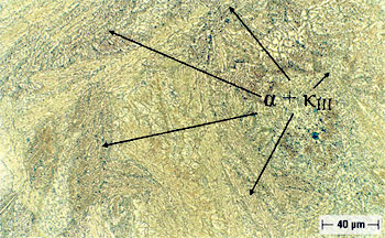 Figure 5. Alloy A (9.4% Al), Solution Annealed, plus Air Cooled and Tempered (AC+T).
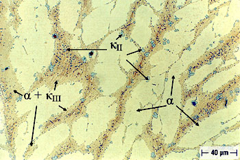 Figure 6. Alloy A (9.4% Al), Solution Annealed and Furnace Cooled (FC).
Alloy B, in the oil quenched (OQ) condition, is free of Widmanstatten α, but does contain equiaxed proeutectoid α, as shown in Figures 7. In addition, Alloy B, in the oil quenched (OQ) condition, contains isolated regions of Bainite and Martensite or α *, as is also shown in Figures 7. When air cooled (AC), the microstructure of Alloy B is quite similar to that developed when oil quenched (OQ). It also develops an equiaxed α microstructure containing isolated regions of Bainite and Martensite or α *, as shown in Figure 8. When subjected to either oil quenching and tempering (OQ+T), or air cooling and tempering (AC+T), Alloy B develops a complex α microstructure, consisting of proeutectoid α containing a fine precipitate of κ III (10) which is ranges from pepper dots to planar lines, as well some retained Bainite and Martensite or α *, which can be seen in Figures 9 and 10. The planar characteristic of the precipitated κ III is more apparent Air Cooled and Tempered (AC+T) condition, as can be seen in Figure 10. When Alloy B is furnace cooled (FC), it contains equiaxed proeutectoid α containing a very fine barely discernible pepper dot precipitate of κ III (10), plus the α + κ III eutectoid, as well as traces of κ II
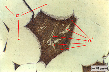 Figure 7. Alloy B (8.1% Al), Solution Annealed and Oil Quenched (OQ).
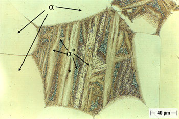 Figure 8. Alloy B (8.1% Al), Solution Annealed and Air Cooled (AC).
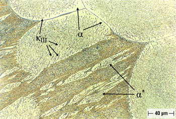 Figure 9. Alloy B (8.1% Al), Solution Annealed, plus Oil Quenched and Tempered (OQ+T).
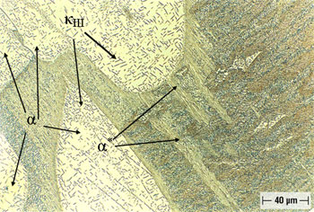 Figure 10. Alloy B (8.1% Al), Solution Annealed, Air Cooled and Tempered (AC+T).
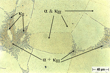 Figure 11. Alloy B (8.1% Al), Solution Annealed and Furnace Cooled (FC).
In the prior quiescent seawater test (14), in Alloy A, the Martensite and Bainite or α*, which was interdispersed between the Widmanstatten proeutectoid α, as shown in Figure 2, was selectively attacked. In Alloy B, the Martensite and Bainite or α*, which was equiaxed and surrounded by proeutectoid equiaxed α, as shown in Figure 7, again suffered from selective phase attack.
General Appearance after Seawater Jet Impingement Tests
Pre-Cleaning Inspection
After 30 days of seawater jet impingement testing at 15 fps (~4.6 mps), all eleven specimens were quite similar in appearance. They were uniformly dark brown, and were either slightly lighter or darker in the region were the jet impinged upon the surface. Slight dishing was also evident in the impingement zones of several more affected specimens.
During 30 days of seawater impingement testing at 30 fps (~9.1 mps), the appearance of all eleven specimens changed dramatically. All the specimens exhibit a mottled appearance, and vary considerably in color, from specimen to specimen and within a specimen. The area of impingement is now quite evident. It also often differs in color from the balance of the specimen which was not subjected to direct impingement. Dishing is more evident than observed at the lower velocity. However, no general conclusions, in regard to the effects of either alloy composition, heat treatment or microstructures can be drawn on the basis of this visual examination alone.
Post-Cleaning Inspection
Following the initial 15 fps test, discernable erosion corrosion was limited to the control, Alloy C, and Alloy A in both the OQ+T and AC+T conditions. The approximate diameters of the impingement zones seen on each alloy are shown in Table 5. All specimens exhibited generally light uniform corrosion. At higher magnifications, selective phase attack was evident in Alloy A and intergranular attack was seen in Alloy B. Unlike the more boldly exposed surfaces, no corrosion was observed at the mounting holes, except for some superficial etching-like crevice attack on some specimens.
| Heat Treatment Code | 15 fps | 30 fps |
|---|---|---|
| Alloy A (9.4% Al) | ||
| OQ | nil | nil |
| OQ+T | 2 - 3 | 10 – 12 |
| AC | nil | 4 |
| AC+T | 2 - 3 | 10 – 12 |
| FC | nil | nil |
| Alloy B(8.1% Al) | ||
| OQ | nil | nil |
| OQ+T | nil | 2 |
| AC | nil | 3 |
| AC+T | nil | 7 – 8 |
| FC | nil | 1 - 2 |
| Alloy C (8.8% Al) | ||
| As-Cast (Control) | 2 – 3 | 6 |
The appearance of the 30 fps specimens following the initial cleaning is presented in Figure 12. The Alloy B specimens are shown on the top and the Alloy A specimens are on the bottom, except for the two specimens on the right, which are both Alloy C. The upper is the control, Alloy C, after testing and the lower is an untested Alloy C specimen. The heat treatment codes, going from left to right, are: OQ, OQ + T, AC, AC +T, and FC. After the 30 fps test, discernable erosion-corrosion damage was again observed on the Alloy A specimens, in the OQ+T and AC+T conditions and the control, Alloy C. In addition, all Alloy B specimens, with the exception of one, in the OQ condition, exhibited erosion-corrosion damage, in the form of dishing, in the impingement zone. The approximate diameters of the erosion-corrosion affected areas are listed in Table 5. In addition, only Alloy A in the OQ+T and AC+T conditions, as well as Alloy B in the AC+T condition, exceeded the control, Alloy C. As shown in Table 6, a variety of other forms of corrosion affected those specimens after being tested at 30 fps. Based upon in-situ inspections, locally attacked areas appeared around the middle of the test period. In some cases, crevice related attack approached that seen in the quiescent test (14).
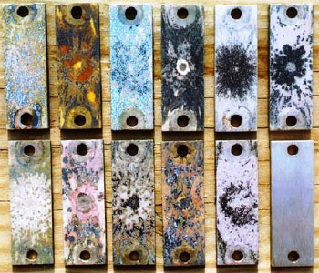
Figure 12. Specimens of Alloy B (8.1% Al) (top row) and Alloy A (9.4 % Al) (bottom row ), Solution Annealed and Subsequently Subjected to Various Heat Treatments, which are, (from left to right): OQ, OQ + T, AC, AC + T, and FC, After Thirty-Day Seawater Jet Impingement Testing at 30 psi and Initial Cleaning. Note that Lower Right Specimen is Untested Alloy C (UNS C95800 Control) and Upper Right is same Alloy after testing. Magnification (~1X).
| Heat Treatment Code | Identified Corrosion |
|---|---|
| Alloy A (9.4% Al) | |
| OQ | A’, B, D, F |
| OQ+T | A, B, C, D, E |
| AC | A, B, C, D’, E |
| AC+T | A, B, C, D’, E |
| FC | A’, B, D, E, F |
| Alloy B (8.1% Al) | |
| OQ | A’, B, C,D’, E |
| OQ+T | A, B, D,F |
| AC | A, B, C, D’, F |
| AC+T | A, B, D, E, F |
| FC | A, B, D, E, F |
| Alloy C (8.8% Al) | |
| As Cast (Control) | A, C, D’, E |
A Jet impingement
A Trace amount of jet impingement
B Crevice at mounting sites
C Crevice at other discrete sites
D Dealloying, general
D Dealloying, localized
E General corrosion F Intergranular, with or w/o grain loss
Paper Number 05223 reproduced with permission from Corrosion/2005 Annual Conference and Exhibition, Houston, Texas