Copper - Super Slim Gas Seals
Copper Applications in Automotive Area
The modern internal combustion engine has advanced significantly over the past 25 years and is now an extremely well engineered machine capable of rotational speed of up to 16,000 rpm. It is worth contemplating what this means. It means that the main shaft of the engine, the crankshaft, rotates at just over 260 revolutions per second. Even the crankshaft in a normal passenger car will rotate at up to 6000 rpm, a startling 100 revolutions per second. The mechanical ingenuity and complexity to achieve this is remarkable.
When you consider how the internal combustion engine works this is quite a feat. The object is to convert the rapid combustion of a gasoline and air mixture, initiated by the spark plug, into rotational motion. We know that the explosion takes place in the cylinder after the mixture has been compressed by the piston, and that the expanding gases force the piston back down the cylinder and this is turn, by a linkage known as the connecting rod, rotates the crankshaft. One of the remarkable engineering achievements is to keep the compressed gases in the cylinder without their escaping during compression, remove them from the cylinder after combustion, and admit a free batch of gasoline and air for the next combustion cycle.
The part of the engine that deals with this problem is the valve and the valve seat. In many modern cars there are now 4 valves for each cylinder, two to admit fresh gasoline/air mixture, (intake valves), and two to remove the spent gases after the explosion, (exhaust valves). A schematic valve and valve seat are shown in Figure 1. In operation the following sequence occurs.
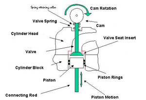 Figure 1. Schematic Section Through Cylinder Head and Block
With all valves closed the gasoline/air mixture is compressed as the cylinder moves upwards. At about the top of its motion the gasoline/air mixture is ignited by the spark plug and the combustion gases begin to expand. Still with all valves closed the gases drive the piston down to the bottom of its stroke. The exhaust valve(s) then opens, and as the piston moves back up the cylinder the spent gases are swept out of the cylinder past the exhaust valve seat. At the top of the piston's motion the exhaust valve closes and the inlet valve open. As the piston again moves downwards it draws a fresh supply of gasoline/gas mixture into the cylinder. At the bottom of the piston's motion the inlet valve closes and with both inlet and exhaust valves closed the piston begins to compress the gasoline/gas mixture, and so repeat the cycle of events.
The interaction between the valve and the valve seat, against which it has to seal, is critical in these operations. The valve seat must be sufficiently wear resistant to avoid wear by the continuous pounding of the valve on it, and the sweep of the gases past it. It has to be strong enough to resist the hammering by the valve and not distort and let out compressed gases at the wrong time. This is especially true of the exhaust valve, which operates at an elevated temperature. The oxidation and corrosion resistance of the valve seat has to be sufficient to prevent damage from impurities in the fuel. In summary the valve seat has a very onerous task to perform and has been the subject of much research and development over the years. As each component is now tailored to meet the duties imposed on it the valve seat is now provided in the form of a separate valve seat insert or vsi. This is fitted into an aluminum cylinder head. By combining the high thermal conductivity, lightweight and castability of aluminum with the high temperature, wear resistant properties of the valve seat insert the best properties of each material are utilised.
The way that the vsi is fitted is important to its function. Figure 2 shows how this is achieved.
Figure 2 shows the round vsi in relation to the circular hole in the cylinder head that it is to fit into. The outside diameter of the vsi, D, is greater than the diameter of the hole in the cylinder head, d. The difference in diameters is exaggerated in the Figure.
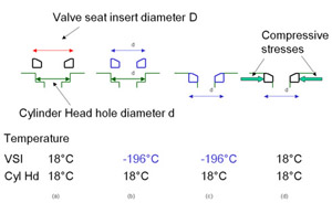 Figure 2. Fitting of Valve Seat Insert
The next step is to cool down the vsi so that its outside diameter D is reduced to that of the diameter of the hole in the cylinder head, d, (or to slightly less than d). Liquid nitrogen is generally used as the cooling medium.
The vsi is then pushed into the hole in the cylinder head and left to regain room temperature.
As the temperature of the vsi rises to room temperature it expands and attempts to regain its original diameter D but it is now constrained by the diameter d of the cylinder head. This constraint causes stresses at the interface between the vsi and the cylinder head, and it is these stresses that keep the vsi in position during the operation of the engine.
In order for this technique to work, the vsi outer diameter and the hole in the cylinder head have to be machined to a high tolerance. This is because the change in outside diameter of the valve seat during cooling is very small. If an iron-based 25 mm (1 inch) diameter valve seat is cooled from 18°C down to the temperature of liquid nitrogen -196°C its outer diameter will decrease by 25 x (196+18) x 11.7 x 10 -4 mm, where the 11.7 x 10 -4 is the coefficient of thermal expansion per °C. This equals 0.25 mm or 0.01 inch. The valve seat diameter changes by only 10 thousands of an inch on cooling to -196°C. This means that the valve seat diameter and the hole diameter in the cylinder head have to be very accurately machined of the valve seat would either not fit in, or would fall out when the valve seat insert reached room temperature.
We now have the valve seat insert in the cylinder head, but what happens when the engine is run and the whole of the cylinder head heats up?
Many modern engine blocks and cylinder heads are made from cast aluminum and the valve seat inserts are almost exclusively iron-based. The aluminum and the iron-based valve seat have different coefficients of thermal expansion and this is where there can be a problem. Consider Figure 3.
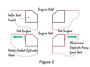 Figure 3. Expansion of Cylinder Head During Engine Firing
When the valve seat insert and the cylinder head are at room temperature the seat is held in place tightly by the compressive stress in the cylinder head, Figure 3a. As the valve seat insert and the cylinder head heat up during the running of the engine a situation develops as in Figure 3b. The temperature at the surface of the valve seat can be at least 200�C. aluminum has a higher coefficient of thermal expansion than iron, in fact, approximately double that of iron. This results in the hottest part of the aluminum cylinder head expanding away from the valve seat insert, leaving a gap. As the cylinder head is cooled by water, the part of the cylinder head at the bottom of the valve seat insert remains relatively cool, and expands away from the valve seat insert far less, in practice, not enough to reduce the compressive stresses to zero. The seat is therefore held in place by the cylinder head at the bottom of the cylinder head hole only. In the past valve seat inserts have been known to drop out of the head during running due to poor dimensional control of the valve seat insert and the machining of the head. Although dropouts are rare today it is still necessary to make valve seat inserts with a height of 6 to 8 mm in order to ensure that the bottom of the seat is cold enough during running to be gripped by the cylinder head.
One solution to this problem has been the development of valve seat inserts that mechanically lock themselves into the aluminum cylinder head and therefore will not drop out. The innovation described here is a second method that involves forming the valve seat in situ on the surface of the aluminum cylinder head. In principle the seat appears as in Figure 4.
Figure 4. Schematic Diagram of In Situ Valve SeatThe seat is formed on the aluminum cylinder head by melting a suitable material on the surface of the aluminum and in the correct position. There are several advantages arising from this innovation. The first is that the valve seat can be very thin as it is metallurgically bonded to the aluminum and cannot fall off. As it is a thin seat, the heat seen by the surface of the valve seat, especially the exhaust valve seat, is conducted away efficiently into the water-cooled aluminum cylinder head. Less material is used, and as valve seat materials tend to be expensive because of the need for the special high temperature strength, wear and oxidation properties, savings are made on materials. The cooling channels in the cylinder head can be moved closer to the cylinder head face so that the inlet valve passage channels the gasoline/air mixture into the cylinder at a more acute angle giving better swirl of the mixture in the head and aiding uniform combustion. The equipment required to cool down valve seats can be dispensed with. Liquid nitrogen is not the easiest of liquids to deal with and in confined spaces would asphyxiate the operator if a spillage occurred. A separate vsi does not have to be made, reducing cost. Machinery to produce valve seat inserts to high tolerance is expensive; it can be dispensed with. Equally the aluminum head does not require such precise machining to accommodate the new technology.
How do we form the valve seat on the aluminum and what material is used as the valve seat? This is where copper and its alloys come into its own.
Copper alloys can be produced which have sufficient wear resistance, and have good mechanical properties at the operating temperature. The innovation consists of making an alloy of copper and nickel and other elements to be described later, and forming a powder from it.
Atomization of molten metallic alloys is common in the powder metallurgy industry and consists of disrupting a molten stream of the metallic alloy with high-pressure water or gas jets. In this innovation the atomization medium was nitrogen gas, used to prevent the powder reacting with oxygen in the air. It was possible to control the amount of oxygen in the nitrogen so as to control the oxygen content of the powder. The disruption causes the molten stream to break-up into small particles. Each particle has the same composition as the next one. In making valve seats the chosen alloy powder is placed on the surface of the aluminum and melted in situ using a high-density energy source, such as laser, plasma or one of the arc welding processes. More than one layer of powder can be to produce the required thickness of valve seat. The most important issue from a materials point of view is the composition of the copper alloy used.
Copper and nickel can be melted together in mixture ranging from 0% nickel to 0% copper without forming any intermetallic compounds between them. They are mutually soluble in each other and produce what is called a solid solution of one in the other when cooled down to room temperature. Copper melts at 1082°C and nickel at 1453°C. Mixture or more precisely, alloys, of copper and nickel melt at temperatures between these two, the melting point increasing with the proportion of nickel added. Nickel improves the corrosion resistance and wear resistance of the alloy but too much nickel increases the melting point to an extent which makes the alloys difficult to manufacture. Nickel is therefore kept within a range of 10% to 30%. This solid solution forms the base for the development of the copper-based alloy.
Other elements that can improve the high temperature properties of this copper-nickel alloy are added to this solid compounds.
Iron, which acts very much like nickel is also added but in quantities between 2% and 15%. This reduces the overall cost of the powder.
Cobalt can only be dissolved in copper in small amounts, but with nickel present more can be added and this results in the formation of high temperature intermetallic compounds being formed during melting and solidification. Below an addition of about 2% there is insufficient high temperature intermetallic compound formed, and above 15%, too much.
Chromium is similar to cobalt and will dissolve sparingly in copper. A little chromium however increases the oxidation resistance of copper significantly and hence it is added in quantities up to about 10%. At the higher concentrations it contributes towards the formation of the high temperature intermetallic compound formation.
Molybdenum, titanium, zirconium, niobium and vanadium are also added in small amounts. They do not normally dissolve in copper to any great extent but the presence of the nickel allows additions to be made. If too much is added the toughness of the copper-nickel alloy are impaired.
Finally silicon is added as it reacts with nickel to form an intermetallic, nickel silicide. It also reacts with the other elements to form high temperature compounds. It is added in quantities from 0.5% to 3.5%.
We now have a solid solution of copper and nickel with additions of other elements that form high temperature intermetallic compounds. These are distributed throughout the copper-nickel alloy and it is these hard particles that control the wear properties of the final material.
Having produced the powder it now has to be applied to the surface of the aluminum. The valve seat is produced by placing powder on the surface of the aluminum and melting it in situ using a laser beam. More than one layer of powder is used to produce the required thickness. There is considerable engineering in designing and building an industrial machine that will do this automatically as can be imagined.
Melting the powder on the aluminum surface showed that there was still a residual problem. When the molten copper-nickel alloy solidified on the surface of the aluminum it was covered in fine cracks. These were due to the stresses that were produced in the alloy by the different coefficients of expansion between the copper-nickel alloy and the aluminum, and the weakness of the copper-nickel alloy at high temperatures during the cooling down period. The answer lay with improving the high temperature strength of the copper-nickel alloy.
The cracking was traced to the silicides that formed during melting and cooling. These were of high density, for example as high as 19.3 g/cc for tungsten silicide (WSi2), compared with 8.9 g/cc for the copper-nickel alloy solid solution. Segregation of the silicides during solidification due to gravity resulted in poor high temperature strength.
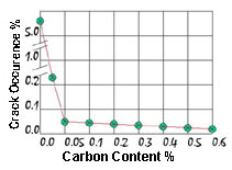 Figure 5.Effect of Carbon Content on Cracking Behaviour
What was found to be important were the concentrations of oxygen and carbon in the powder. With sufficient carbon present the additives prefer to form carbides rather than silicides as carbon is a more reactive element. When the carbon is used up the remaining additives then formed silicides, but now they use the existing carbide particles to grow on. Too much carbon can be deleterious and the level is kept between 0.05% and 0.5%. The result of this deposition of silicide on carbide is that the average density of these high temperature particles is far less, gravity segregation is avoided, and a homogeneous distribution of particles throughout the copper-nickel solid solution results. The effect of carbon content on cracking is illustrated in Figure 5.
The final step was to control oxygen in the alloy. With sufficient oxygen present the weld beam has a protective layer of silicon dioxide, SiO2, on it and this prevents the weld bead from cracking. The concentration has to be kept within limits of 0.03% to 0.05%.
By observation it was seen that there was a relationship between the carbon and oxygen contents in satisfactory copper-nickel alloys. This was that
%O2 >= 0.8 x %C + 0.04
This means that the percentage of oxygen in the powder has to be equal or greater than 0.8 times the percentage of carbon in the powder plus a further 0.04 %. This effectively is shown in Figure 6. All of the green circles showed less than 0.05% of all samples were cracked, the red unfilled triangle between 0.05 and 1.0% cracked, black Xs are more than 1.0% cracked, and the filled red triangle all had pinholes in the weld surface. It is considered that a level of cracking of less than 0.05% is acceptable for industrial practice.
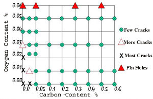 Figure 6 . Relationship Between Carbon and Oxygen Content
During atomization it was also noted that the new alloys did not cause the nozzle to become blocked, that is the nozzle through which the molten stream dropped to be atomized by the nitrogen gas jets, an added bonus, and one that makes the production of these powders more economical.
After the seat has been formed a final machining step is necessary to form the face against which the valve will seal.
In operation the added elements strengthen the copper-nickel solid solution and ensure that it has sufficient mechanical strength. The nickel addition and especially the chromium addition increase the oxidation and corrosion resistance of the seat towards the hot exhaust gases. The hard particles, which can be as hard as 1200 to 1300 Hv, something like an alumina ceramic, also strengthen the solid solution by a process known as dispersion strengthening. They also significantly improve the wear resistance of the copper-nickel solid solution. Held in the copper-nickel alloy the particles resist wear and prevent the valve rubbing against the softer copper-nickel alloy.
At temperatures of about 500°C or more it is known that the silicide particle will decompose and in doing so convert the silicide to an oxide as there is a significant amount of oxygen present in the petrol/air mixture. In particular the oxides are likely to be molybdenum, tungsten, niobium or vanadium oxides, all of which have low melting points. The oxides form a liquid on the surface of the copper-nickel alloy providing a lubricating effect and preventing the copper-nickel alloy from contacting the valve itself. The copper-nickel alloy also has a higher thermal conductivity than any of the iron based valve seat insert materials and hence cooling of the vale seat face is more efficient, especially as the seat itself is so thin.
The Toyota Motor Corporation, Japan, developers of the new material, have also designed and built prototype computer operated laser equipment for automatically forming these in situ valve seats.
In summary the seat has all of the attributes required of an efficient valve seat thanks to the thermal conductivity of copper and its ability to form copper-nickel alloys with dispersion hardening particles, which are oxidation and corrosion resistant and have high strength at the operating temperatures.
Innovations used US Patent 5,843,243, as the basis for this article.
Also in this Issue:
- Copper - Super Slim Gas Seals
- High Tech House Runs on Copper
- Copper - Keeping Up Appearances
- Copper/Cobre 99 a Success