- NO! to Value Engineering
- Robust Electrical Architecture
- Recommended Practices
- MIT follows Recommended Practices for High Power Quality
- Grounding System Exceeds Code
When one of the nation’s leading technical institutes set out to design a new center for computer, information and intelligence sciences, top-quality electrical power was high on the list of must-have features. Why? Because all of the sensitive electronic equipment in the center would need clean, stable power, or the equipment simply would no work as it should.
And so, in 1999, when the Massachusetts Institute of Technology began planning the Ray and Maria Stata Center as part of its campus redevelopment program, planners gave very careful attention to the new structure’s electrical and grounding systems.
The 720,000-sq ft Ray and Maria Stata Center, which opened in May 2004, consists of two nine-story towers: the William H. Gates Building and the Alexander W. Dreyfoos Building, each named for their respective principal benefactors (Figure 1). The complex also includes an auditorium, four classrooms, several 600- to 800-sq ft server rooms, a child-care center, a food services facility, a fitness center, outdoor gathering spaces, two levels of below-grade parking and a service facility. Design highlights are featured at MIT website.
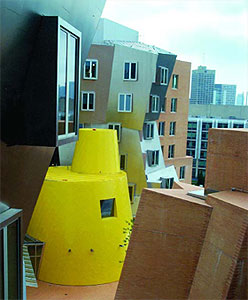
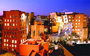
Figure 1. The 720,000-sq ft Ray and Maria Stata Center at MIT, designed by Frank Gehry, is not only one of the most striking architectural works on a U.S. college campus today: it is also a building designed for optimum power quality— an absolute necessity for the sensitive electronic equipment the facility contains.
Not only does the center’s electrical infrastructure incorporate the latest in current technology, it is deliberately designed with sufficient size and flexibility to accommodate the institute’s future needs. Stata is also a people-friendly building and, arguably, the most eye-catching structure to be found on an American college campuses today (top image and Figure 1).
NO! to Value Engineering
Not evident on the building’s exterior, but clearly visible in its transformer vaults and electrical rooms, is the level of care the architects and engineers took with the building’s electrical and grounding systems.
Robert Cunkelman, P.E., is a senior engineer in MIT’s Department of Facilities. He was a member of the center’s planning team and was also present when the complex was designed and built. He emphasizes that “There was never any intent to cut down on quality. We did hear a lot of suggestions during the design phase over value engineering — that is, making the system seem ‘just as good’ at lower first cost — but we said ‘NO!’ to most of them,” adding that life-cycle cost was the primary financial consideration.
“When it comes to power quality,” he says, “it just doesn’t pay to nickel-and-dime the electrical system, because the difference in price you might see at the beginning is not worth the net-value loss over time. Energy efficiency is equally important because it involves not just life-cycle cost but also helps the environment, and that’s something MIT is very clear about.”
Cunkelman also points out the strength and flexibility designed into the center’s infrastructure. “The electrical system is robust. Its design peak load, 4.9 MW, might seem overbuilt, in that we’ve only seen a maximum of 3.2 MW so far. But, like MIT’s other permanent buildings, the Stata Center was designed for future load growth.”
Christopher J. Terman, a senior lecturer in MIT’s Electrical Engineering and Computer Science Department, was chairman of the building committee. He readily supported Cunkelman’s observations, adding that “The Stata Center was built from the user’s point of view — and that includes me, since my office is in the building. We insisted on a very reliable power system, so the building is powered with double- ended switchgear through two separate loops. We have a central uninterruptible power supply (UPS), and there is local UPS backup protection on individual computers.” Terman admitted the center doesn’t have a conventional lightning protection system, but he noted it wasn’t considered necessary, since much of the building’s exterior is clad with stainless steel, all of which is grounded through the structure itself.
Robust Electrical Architecture
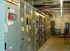 Figure 2. Transformers and controls in one of two double-ended substations serving the Stata Center. In each substation, a dual-rated (2000/2667- kVA), 13.8kV-480Y/277V, cast-coil, copper-wound, 115° C rise, Square D transformer feeds 480-V power to one of the towers via two copper buses. Lower floors have a more conventional architecture. Grounding connections from the main ground bus (not visible in photo) are made to a 500-kcmil copper ring ground that completely surrounds the building’s 1,400-ft perimeter.
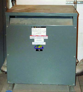 Figure 3. A 112.5-VA, 480V-208Y/120V distribution transformer, one of several installed on floors six through nine in the towers. Larger units are found on lower floors. The electrostatically shielded Square D transformers are copper-wound and contain low-loss silicon steel core laminations. They meet NEMA TP-1 efficiency standards and help reinforce MIT’s strong support for environmental stewardship.
The center’s electrical system is fed by MIT’s 13.8-kV underground grid. MIT operates its own central power plant and a 20-MW gas-fired cogeneration plant. There are also ties to the local utility grid. Heat for the Stata center is supplied by steam from the central plant. Air-conditioning chillers at the plant are also steam-driven.
Two double-ended substations located in the center’s subbasement feed each of the building’s towers, respectively (Figure 2). Each substation is equipped with a dual-rated (2000/2667-kVA), 13.8kV-480Y/277V, cast-coil, copperwound, 115°C rise, Square D transformer and state-of-theart power monitors and controls. A 1500-kW diesel-driven generator provides emergency power for ventilation, elevators and other safety-related equipment.
Two 800-A, 480-V copper buses from each substation feed floors four through six and seven through nine, respectively, in each tower. Several K-rated, 480V-208Y/120V, electrostatically shielded transformers (Figure 3) distribute power to subpanels on each floor. The transformers range in size from 112.5 kVA to 225 kVA. All are copper-wound, and all meet NEMA TP-1 (Energy Star) efficiency levels. Additional 13.8kV-277Y/480-V transformers handle lighting loads, and a pair of smaller transformers supplies power to rooftop equipment for each tower. Large 480-V motors in the building are powered independently from the buses.
Recommended Practices
The National Electrical Code® (NEC) is intended to ensure safety, and it contains few provisions dealing specifically with power quality. Those issues are addressed in the form of recommended practices in publications like the Institute for Electrical and Electronic Engineering’s familiar “Green Book” (IEEE Std 142) and “Emerald Book” (IEEE Std 1100). Not surprisingly, the Stata Center’s electrical and grounding systems incorporate many of those recommended practices.
For example, the sensitive electronic equipment in the Stata Center is a powerful source of harmonic distortion, as are the variable frequency drives on motors for the center’s many ventilation fans. Among other problems, harmonics can give rise to high currents on circuit neutrals, a potential fire hazard. Simple, recommended practices to reduce this risk include doubling the neutral conductors, upsizing them or installing separate neutrals for each phase.
For R.G. Vanderweil Engineers, Inc., the Boston-based firm that designed the Stata Center’s electrical system, doubling the neutrals was only one of many steps taken to ensure good power quality. Robert Chaves, Vanderweil’s lead engineer on the project explains: “We called for 200% neutrals on all feeds to panels serving laboratories and offices where the computers are. We also separated these “sensitive” circuits from other circuits, and we specified that they be fitted with isolated grounds, that is, their green wires run directly to the main ground bus. That practice is intended to reduce noise on the circuits. There are full-size green wires for each circuit, of course, and we never rely on conduit or raceways as ground return paths, even though the Code permits it.
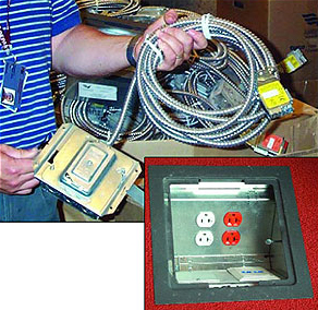 Figure 4. Modular “plug and play” outlets supplied by America Cable Systems, an AFC Company. Top: module with attached cable and connector. Bottom: outlets installed in raised flooring. Electrical specifications call for a maximum of six outlets per branch circuit, a recommended practice intended to reduce the effects of harmonics on sensitive circuits. All branch circuits also have fullsized ground wires. Cable armor, conduit and raceways are grounded but are not used in place of the primary grounding conductor.
“The K-rated transformers that feed sensitive circuits are another recommended practice. They’re better able to tolerate heat caused by harmonics. We also called for electrostatic shielding on those transformers to reduce noise. The transformers are all copper-wound, and have high efficiency ratings.
“We limited the number of outlets on sensitive branch circuits, which is another recommended practice that helps improve power quality. Vanderweil’s specs call for a maximum of six outlets per branch circuit in such cases. There might be more outlets on non-computer circuits, but those circuits are usually not subject to excessive harmonics.
“Floors two and higher have raised floors, and the entire power system on those floors is what we call plug-and-play. All circuits and outlets are modular, supplied by American Cable Systems (Figure 4). The idea is to provide the building and its electrical system with maximum flexibility.”
MIT follows Recommended Practices for High Power Quality
Vanderweil Engineers designed electrical and grounding systems for MIT’s $250 million Stata Center that follow recommended practices for optimum power quality. Key elements include:
- Installation of a 500-kcmil bare copper ring ground and multiple “triangulated” copper-clad electrodes — to ensure less than 5 ohms resistance to ground.
- The use of copper-wound, K-rated transformers — to help accommodate harmonic currents and maintain high efficiency.
- Installation of 200% neutrals from distribution transformers to the sensitive load panels and the use of dedicated branch circuit neutrals — to guard against overloads due to triplen harmonics.
- Installation of full-sized grounding conductors in all circuits instead of using cable armor, conduit or raceways as the principal ground return path — to ensure that low ground resistance to the points of use remains low for the life of the building.
- Dedication of sensitive branch circuits to computers, laboratories and offices and separation of those circuits from branches serving nonsensitive equipment — to shield sensitive equipment from electrical noise.
- Limiting the number of outlets on sensitive branch circuits to six or less — to reduce the magnitude of harmonic currents.
- Installation of isolated grounds (IGs) in all sensitive circuits — this practice provides additional protection against RF noise and other voltage irregularities.
- Installation of TVSS protection at substations and at points of use — layered protection of this type assures maximum protection from voltage surges.
Grounding System Exceeds Code
Based on safety concerns only, the NEC identifies 25 ohms as an acceptable ground resistance for a made electrode; however, sensitive electronic equipment operates best when resistance to ground is considerably lower. Recommended practices suggest that five ohms or less is preferred for sensitive equipment, and that is the number Vanderweil Engineers specified as a maximum value.
“We actually got one ohm or less at the substations,” says David J. Courtemanche, P.E., a Vanderweil Engineers vice president and its chief electrical engineer. “The basis for the building’s grounding system is a 500-kcmil ring ground buried three feet below grade, completely surrounding the property. The ring is bonded to triangulated electrodes at the building’s corners and around the 1,400-ft periphery, as well as to the main grounding bus at each of the substations. The Stata Center is a concrete building, and the slurry walls extend to 75 ft below grade. We did pick up connections to reinforcing steel at several locations, but those aren’t primary grounding points. Instead, we designed a series of 12 grounding risers up through the building to provide safe and effective grounding connection points. The risers consist of AWG 4/0 copper cable terminating at ¼-in x 2-in copper grounding buses to which all electrical distribution equipment and telecommunications systems equipment are bonded. With all of that, this is a very well grounded building.”
The Principals
 Robert P. Cunkelman, P.E., is a senior engineer in MIT’s Department of Facilities. He was a member of the planning team for the Stata Center and was present through the building’s design and construction phases. Mr. Cunkelman can be reached at (617) 253-6371, fax (617) 452- 2342, email [email protected].
 Christopher J. Terman is a senior lecturer in MIT’s Department of Electrical Engineering and Computer Science. Mr. Terman was chairman of the Building Committee for the Stata Center. His office in the center allows him to enjoy the building’s high power quality on a daily basis. Mr. Terman can be reached at (617) 253-6038, email [email protected].
 Robert Chaves is a senior electrical engineer at R.G. Vanderweil Engineers. The Stata Center’s electrical and grounding systems were his direct responsibility. Mr. Chaves can be reached at (617) 423-7423, fax (617) 350-7186, email [email protected].
 David J. Courtemanche, P.E. is vice president, R.G. Vanderweil Engineers, a multidisciplinary consulting engineering firm specializing in M-E-P Systems for buildings, central heating and chiller plants, power generation, and transmission and distribution (T&D) design, see www.vanderweil.com. Mr. Courtemanche can be reached at (617) 423-7423, fax (617) 350-7186, email [email protected].