![]() Download PDF Version [572 Kb]
Download PDF Version [572 Kb]
- New Infrastructure
- Fully Redundant Electrical Systems
- Going Beyond the Code "Every Day"
- Back-up Power
- Single-point Grounding
- Grounding Overhead and Underfoot
- Planned Maintenance Important
 Data centers have quietly become a significant portion of the national electrical infrastructure. The Federal Government alone was operating more than 1,100 in 2009.1 Along with commercial facilities, the data centers are huge electric power users. The U.S. Environmental Protection Agency once projected that such centers would account for three percent of all electricity consumed in the country in 2011, but they surpassed that figure a year earlier. At a 10% cumulative annual growth rate (CAGR), consumption could double well before the decade is out.2 Steve Collins, an Associate with Vanderweil Engineers, a leading engineering firm (see description below), estimates that the gross power consumed by these "server farms" will increase significantly as centers continue to proliferate and unit electrical loading in them rises to a projected 1,500 W/sq ft.
Data centers differ from most other industries in that electrical power reliability and power quality are exceptionally high. A TIA 942 Tier 4-rated facility will have 100% reliability, but, allowing for human error, the standard allows or projects at least 99.995% average availability (0.4 h average annual downtime over five years), yet, the percentage is often higher than that. High power quality implies stable, correct voltage with undistorted waveform. Equipment is correctly installed, rigorously maintained, and, not incidentally, dependent on miles of copper for reliability.
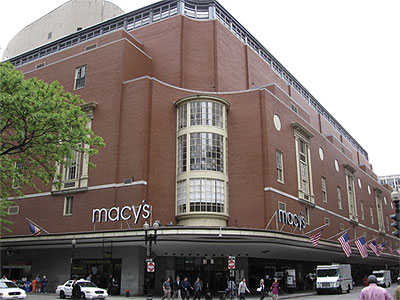
All of which brings us to One Summer Street, an 800,000-sq ft data center located in Boston's "Downtown Crossing" (Top photo). Don't be misled by that Macy's sign; the data center occupies most of the 2½-acre, city-block-size building, including systems infrastructure located in the basement levels and multiple roof areas. As a data center, its advantages include a potentially large nearby customer base; eight utility feeds fromtwo substations for reliable power and service by no less than 40 national and international communication providers. The neutral colocation center is a true carrier hotel. It's the largest and arguably the most significant data center facility in the entire New England region.
Back to TopNew Infrastructure
The Markley Group built, owns and operates One Summer Street. The company is a leading data center developer with properties in the U.S. and Europe totaling more than three million square feet. Markley Group acquired the 70-year-old Macy's building in 1999 and has invested more than $150 million to create the kind of sophisticated infrastructure a facility of this importance requires.
That infrastructure is the subject of this case study. The building itself was exceptionally sound, with features such as secure walls and high ceilings not found in some purpose-built centers (Figure 1). Its large, multitiered roof area was ideal for emergency generators, chillers and related equipment (Figure 2). And, with Macy's continuing to occupy the lower floors, the center itself is hidden in plain view ― not a trivial security consideration.
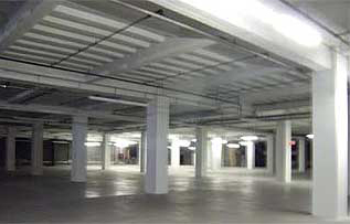 Figure 1. Fifteen-foot ceilings at One Summer Street enable installation of 24" to 36" raised floors while maintaining ample overhead space for cable trays and racks.
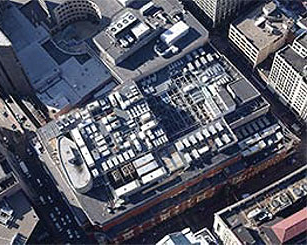 Figure 2. More than 30 generators and HVAC equipment nearly blanket the building's 2½-acre, mulitiered roof. A total of 30 MW of emergency power plus more than 10 MW of rotary and battery UPS power ensure seamless transfer. Future build-out to 40 MW of generation will accommodate growing electrical loads.
The building's old electrical infrastructure was another story. Energy-hungry data centers didn't exist 70 years ago, so totally new electrical, grounding, IT and HVAC systems had to be installed. Power density exceeds 400 watts per square foot. The Markley Group assigned the building's makeover to Vanderweil Engineers, a Boston-based firm with more than 50 years' experience with commercial, industrial and public facilities, including data centers. Besides design, Vanderweil undertook construction administration and oversight, recommended subcontractors, and even conducted detailed inspections during construction. They were also the systems-commissioning and integrated testing agents.
Back to TopFully Redundant Electrical Systems
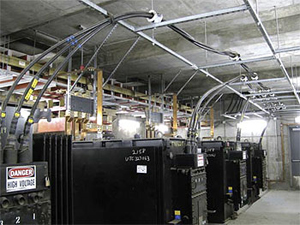 Figure 3. Four of eight 13.8 kV-480 V utility transformers located in a vault at One Summer Street. A similar set of transformers in a separate vault form the other half of the double-ended utility feed. Copper buswork seen at the upper left feeds distribution switchgear located in the basement. Utility ground straps are visible on the floor and rear wall.
The center's 480-V power is distributed from the basement to server floors via ten 4,000-A copper bus risers. Four 5,000-A bypasses connected to the 6000-A rated switchgear enable load-switching among the riser feeds in the event one service should fail (Figure 4). Power bus risers are physically separate from IT/data risers in order to avoid electrical noise on sensitive circuits. Approximately one hundred 480 V-208/120 V distribution transformers of various sizes feed servers and convenience outlets (Figure 5). Additional 480/277 V transformers serve lighting and HVAC requirements. All distribution transformers are copper-wound, dry-type, K-rated (mostly K13 and K20) units meeting NEMA TP-1 efficiency standards.
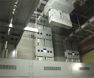 Figure 4. Switchgear (in cabinets, bottom) and three of the ten 480-V, 4,000-A copper bus risers that feed power to upper floors (top of photo). Four 5,000-A bypasses enable switching among primary feeds.
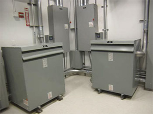 Figure 5. Two (of more than 100) redundant 480 V-208/120 V distribution transformers feed customers' servers and convenience outlets. All sub-distribution transformers are copperwound, dry-type, K-rated, and meet NEMA TP-1 efficiency standards.
Individually fed power distribution units (PDUs) feed branch circuit panels and remote power panels (RPPs). For redundancy, branch circuits are extended to each server cabinet in an "A+B" configuration from two unique PDUs. The redundancy at the branch circuit improves reliability and permits either half of the electrical system to be shut down for maintenance without disrupting power (Figure 6).
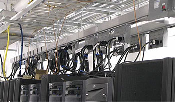 Figure 6. Power is fed to equipment cabinets via power distribution units (PDUs), seen here. Each PDU/cabinet is served by a minimum of two branch circuits providing 2N redundancy. Copper grounding conductors are run in ladder racks, above.
Going Beyond the Code "Every Day"
The National Fire Protection Association's (NFPA) National Electrical Code® (NFPA 70: NEC) is concerned primarily with safety. It doesn't fully address reliability or sensitive electronic equipment, which are dealt with in publications such as the Institute for Electrical and Electronics Engineers (IEEE) "Gold"3 and "Emerald"4 books, and the Telecommunications Industry Association standards5, among others. Data centers could not guarantee the levels of reliability and power quality required if they were designed and built to the Code's minimum requirements. Electronic equipment ― especially IT and telecommunications equipment ― requires higher reliability and better power quality than the Code's minimum standards provides for.
For example, Code-mandated wire sizes and voltage drop limits involve safety issues (overheating) but can also affect reliability and power quality. Don Esson is the Markley Group's facilities manager at One Summer Street. "The NEC is a minimum standard," he says, "and we supersede it every day in every project we work on. Working strictly to Code practice, we would be running AWG #12 wire for a 20-A branch circuit. Our standard is to run #10 instead. It can handle 1.5 times the ampacity; it's more robust and therefore more reliable. Also, with #10, the customer has the built-in flexibility to upsize to 30-A receptacles in the future if he wishes. There's very little increase in materials and labor costs, but reliability improves and you usually don't have to upsize the conduit when upsizing copper, as you would with aluminum.
"We limit the number of outlets per branch circuit to between four and six, except for IT circuits, which are one-on-one, or actually two-on-one since all IT branch circuits are double-ended: each receptacle contains two #10 phase conductors and a neutral conductor for the "A" circuit and two more for the "B" circuit, plus separate full-size grounding conductors.
"Voltage drop is another important consideration. We always bump up one conductor size, so if you had a 100- A feeder, by Code you would typically run #4. We would probably run that with #2 wire. Voltage drop gets taken out of the equation at that point. The Code permits a two percent drop for feeders and three percent for branches, but we hold that to just two percent."
Back-up Power
The facility has approximately 20 MW of emergency generator capacity, and more than 10 MW of rotary (flywheel-type) and battery power in multiple UPS systems. Power cables from generators and UPS systems are in multiple sets of 500–750-kcmil conductors. "Backup power is extremely important for a facility such as this," says Mr. Esson, "and, while value engineering may give us a choice to save on cost, it is important for us to utilize quality components to maintain system reliability. Equipment testing, commissioning and integrated testing, along with proper scheduled maintenance, are essential for these equipment items and systems."
Single-point Grounding
Christopher McLean, PE, LEED AP, is Vanderweil's Electrical Engineer at One Summer Street. From his employer's side, he's been personally responsible for almost all of the power distribution improvements during the several years he's been on the project. That responsibility includes the all-important grounding system. Prior to the inception of the Markley Group's ownership, tenants were all treated individually, which resulted in each tenant having their own electrical service entrance equipment, a scenario that created multiple ground current loops throughout the building.
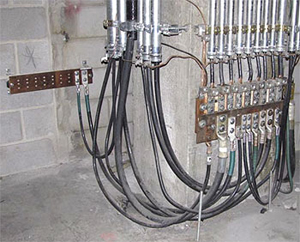 Figure 7. The main grounding bar at One Summer Street is a three-foot by one-foot copper plate (right) located in the subbasement. All grounding conductors in the building's two grounding system branches terminate here. The smaller bar at left rear is an extension of the larger bar.
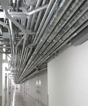 Figure 8. Typical conduit runs at One Summer Street illustrate why the center relies on separate internal green wires rather than conduit itself as the grounding path. Copper is a better conductor than conduit steel. And, if conduits were used for grounding, thousands of connections and fittings would have to be inspected, torqued and tightened periodically, a hopeless task.
"Grounding is critical in a data center," says Mr. McLean. "Computer equipment is very sensitive to harmonics and high currents, so you want to isolate the equipment from transients, high frequencies and ground currents that might be placed on your grounding system at points of voltage and current transformation. We only have two levels of transformation, from 13.8-kV utility service to 480 volts and again from 480 volts to 208/120 volts, but they occur at hundreds of points where you're connecting neutral to ground at transformers, switchboards and other separately-derived systems. Any of those points could feed transients, stray currents or harmonics back to the computer equipment. Our enforcement of a single-point grounding system prevents that."
The single point Mr. McLean refers to is the center's main grounding bar, a one-foot-high by three-feet-wide copper plate located in the building's subbasement (Figure 7). To that plate alone are bonded all ground leads from the building. There are actually two risers for the grounding system: one for the power distribution system, which includes generators, transformers and UPS equipment; the other for IT and communications circuits. Separating the two systems isolates IT/comm equipment from noise, harmonics and fl oating ground currents that may be present at ground-to-neutral bonds. The two systems are bonded together only at the main grounding bar.
Extending "earthward" from the main grounding bar are multiple connections to building steel in walls and the subbasement floor, as well as to the water main on both sides of the meter. The building stands just 23 feet above sea level, making the floor and footings effective earthing points (Ufer grounds). Design ground resistance is five ohms.
Connections to building steel (including the basement floor) are made only from the main grounding bar. McLean explains that "All of the hundred-plus transformers throughout the building are connected to ground, plus we have many neutral-to-ground currents from unbalanced single-phase sources that ultimately put current to ground someplace. Had we connected to building steel from several points on the grounding system, the entire building steel system could have become one giant ground loop. That could compromise the ground-fault settings in switchgear and cause problems everywhere in the building. By connecting from only one point — the main grounding bar in the basement — we've created a very robust grounding system that isolates those problems."
Conduits are also bonded to the grounding system only at the main grounding bar to create a complete system. However ― and despite it being permitted by Code ― conduit is never used as the only grounding conductor. McLean explains: "In almost all instances, conduit would not be an effective grounding path. We always run at least one separate grounding conductor for each feed. Where we run two parallel feeds in the same conduit, each gets its own green wire. "One look at Article 250 in the Code would show you that the ampacity of the required copper grounding conductor is much higher than that of either galvanized conduit or electrical metallic tubing, EMT. Also, if we used the conduits as grounds, thousands of fittings and interconnections would then have to be inspected, torqued and tightened periodically, whereas a separate green wire only has to be inspected and torqued at the two end connections (Figure 8)."
Grounding connections between the main grounding bar and the two grounding system branches are made through separate risers in the building's corners, one for power distribution and one for IT equipment. Plans called for adding two more ground risers in the near future. Conductors from the main bar to the building floors are sized at 750 and 1,000 kcmil. They terminate at one-foot by three-foot copper grounding bars at each floor (Figure 9). Smaller conductors lead from those bars to multiple four-inch by one-foot collector bars located high on walls throughout the floor space (Figure 10). Two sets of large and small grounding bars per floor serve power distribution and IT equipment, respectively.
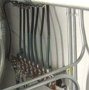 Figure 9. A 1,000 kcmil grounding conductor (lower left) from the main grounding bar terminates at a ground bar serving one floor from one of the building's two ground risers. Smaller conductors bonded to the main floor bar (upper cables) lead to collector bars on the floor.
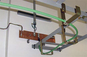 Figure 10. Multiple grounding collector bars are mounted on walls in server rooms. The AWG 2/0 conductor, top, leads to the riser bar, while #2 green cable, bottom, is a collector bus for a row of cabinets. Conductor sizes vary with clients' needs.
Grounding Overhead and Underfoot
 Figure 11. Green grounding conductors bond individual cabinets to an overhead collector bus. In this example, cabinet grounds are AWG #6 and the collector bus is #2, but larger sizes may be used
Equipment racks are grounded by overhead and underfloor systems. For overhead systems, individual cabinets are grounded with AWG #6 or #4 leading to overhead ladder racks. Grounding conductors from all cabinets in a row are bonded to a collector bus cable run in the racks. It may range from #2 to 4/0 in size depending on need (Figure 11).
Collector bus cables are directed to the nearest collector bar. The ladder racks themselves are also grounded via the bars (Figure 12). Cable trays carrying 208-V power to servers are grounded to separate collector bars serving the power distribution branch of the grounding system.
The raised-floor grounding system consists of grids of AWG #2 and 4/0 bare copper, (Figure 13). For approximately every 3000 sq ft of raised-floor area, one 4/0 grounding conductor is run from the grid to the wallmounted collector bar.
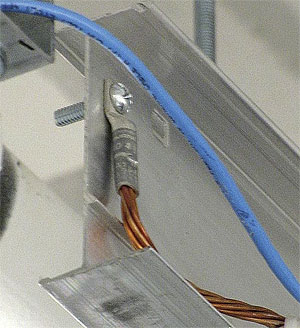 Figure 12. Overhead cable trays and ladder racks are jumpered and grounded with AWG #2 bare copper. These conductors, along with the cable bus that collects ground leads from individual cabinets, are connected to the nearest wall-mounted collector bar.
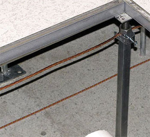 Figure 13. Bare copper grounding conductors are shown strung under a section of raised floor. Raised-floor grounding conductors from approximately every 3,000 sq ft of floor area are connected to a wall-mounted collector bar.
Planned Maintenance Important
One Summer Street clearly has well thought out and executed electrical and grounding systems, but even these systems can degrade over time: Connections loosen, contact resistances rise and loads change, producing unexpected effects. The electrical and grounding systems at One Summer Street are, therefore, inspected and maintained according to a written program. Grounding connections are checked for tightness on a fixed schedule and re-torqued as needed. Power quality is monitored to ensure clean waveforms and voltage stability. Emergency generators and UPS units are periodically exercised. Systems are also regularly upgraded to meet changing needs.
Data centers are indeed mission-critical facilities with unique reliability and power quality requirements. Toptier designers and owners like Vanderweil Engineers and The Markley Group, respectively, clearly provide their clients with both of these elements at One Summer Street. The key components are not surprising: sound design, careful installation, attentive management, regular maintenance ... and the correct use of copper for circuitry and grounding.
The Principals
 Donald J. Esson is the chief infrastructure engineer at One Summer Street. He can be reached at 617.451.2303 and at [email protected].
 Stephen R. Collins is an Associate at Vanderweil Engineers and has been the project manager for the One Summer Street projects. He can be reached at 617.423.7423 and [email protected].
 Christopher K. McLean, PE, LEED AP, is an electrical engineer with Vanderweil Engineers assigned to One Summer Street. He can be reached at 617.574.8184 and [email protected].
 Founded in 1950, Vanderweil Engineers is a full-service engineering firm committed to developing innovative solutions and solid working partnerships. It has earned a 90% repeat business ratio and is consistently ranked among the top U.S. engineering firms. Vanderweil can be reached at (617) 423-7423.
 Over the past two decades, the Markley team has developed thirteen data center and telecom buildings throughout Europe and North America, with Markley's flagship facility located at One Summer Street in Boston. Markley Group can be contacted at (213) 622-3000. The Boston facility, in particular, can be contacted at (617) 451-6464.
Footnotes
 Office of Management and Budget
- Energy Star Program
- The IEEE Gold Book: IEEE Standard 493, Recommended Practices for Grounding of Industrial and Commercial Power Systems, Institute of Electrical and Electronics Engineers, February 2007.
- The IEEE Emerald Book: ANSI/IEEE 1100, Recommended Practice for Powering and Grounding Electronic Equipment. Institute of Electrical and Electronics Engineers, December 2005.
- TIA-942: Telecommunications Infrastructure Standard for Data Centers, Ed. V, March 2010, Telecommunications Industry Association.