- Two Severe Lightning Strikes
- Lightning Took the Natural Path
- Good and Not-so-good Components
- Bad Vibrations
- New Grounding System
- Guy Anchor Grounds
- Very Low Ground Resistance = Ongoing Protection
- Sound Advice from a Pro
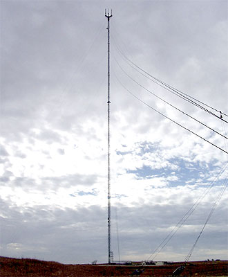 Radio and TV remain the primary emergency information sources for many Americans, especially those folks living in rural or agricultural regions. The “Siouxland” portions of South Dakota, Nebraska and Iowa are good examples. The tri-state region is centered roughly on Sioux City, Iowa, and is mainly comprised of farmland and prairie. Among the network-affiliated television stations serving the area are KPTH and KMEG. The two 1,000-kW stations transmit from a single 1988-foot tower near Hinton, Iowa (Top photo). The tower, operated by KPTH, is among the 50 tallest guyed masts in the continental U.S., making it an attractive target for lightning, especially in the thunderstorm-prone Midwest.
Two Severe Lightning Strikes
The Iowa prairie hosts 50 or more thunderstorms annually, according to the National Weather Service. That’s an accepted fact of life in the Midwest, and it’s not devastating. But, two hits to the KPTH-KMEG tower in June 2001 and September 2003, respectively, were downright terrifying in the sense of what could have happened.
As with most other lightning incidents at the tower, the two strikes in question followed guy cables to earth, but these hits were apparently stronger than usual,1 packing enough energy to damage two of the massive, reinforced concrete anchors that secure the cables (Figures 1 and 2). The anchors extend between 40 and 52 feet underground.
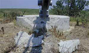 Figure 1. Lightning damage to the outer "B" cable anchor from a June 2001 strike. The strike ejected 100-lb blocks of concrete several yards from the anchor after bypassing the existing high-resistance grounding system.
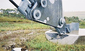 Figure 2. Damage to the outer "A" anchor from October 2003 strike. This event led to an upgrade of the entire facility's grounding and lightning protection system.
 Figure 3. Plan view of the KPTH-KMEG tower guys with newly emplaced grounding rods. The improved grounding system installed at the KPTH-KMEG tower includes multiple deep electrodes to achieve very low resistance to earth. The originally installed system utilized 8-ft electrodes, some of which had ground resistances as high as 200 ohms. See detail of shaded area at Figure 11.
Detailed Image
What if the next big hit succeeded in destroying or seriously damaging an anchor? Would the tower collapse, and even if it didn’t, would the stations be off the air for months while repairs were made? And, more to the point: why did lightning damage the concrete anchors in the first place, since the anchors, the guy cables and the tower itself were protected by an elaborate grounding system?
Or were they?
For answers, station management turned to Computer Power & Consulting Corporation, an Omaha, Nebraska-based company with more than 30 years’ experience with lightning protection, grounding and power quality issues. Martin Conroy, the company’s founder and president, was not surprised at what he found.
Back to TopLightning Took the Natural Path
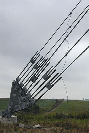 Figure 4. Original grounding connection at an outer anchor. High ground resistance and questionable connections enabled lightning to bypass this grounding system, causing damage to the anchor concrete, lower left. Note the zigzag path of the grounding conductor that reduced the system's effectiveness.
“For example, we noted that the two big strikes occurred on the outer “A” and “B” sets of guys, whose anchors happen to be situated at the highest elevations on the site and are, therefore, set in relatively dry soil. You’d expect soil like that to have high electrical resistance and that the grounding system at those points might not be fully effective. Sure enough, we found the ground resistances of the existing electrodes at the “A” and “B” ancho
“Next, we looked at how the guy cables were grounded. The grounding connections to the guy cables are upstream of the anchors (Figure 4) in order to keep the anchors out of the lightning’s path,” Conroy explains. “There were some other problems with the connections that I’ll get to in a moment, but it’s reasonable to conclude that the lightning bypassed the high-resistance grounding system entirely and, instead, preferred the natural, lower-resistance path to earth offered by the concrete and 40- to 50-foot-deep reinforcing rods in the anchor itself.
“Remember, reinforcing rods in concrete footings are widely used as Ufer grounds in all sorts of buildings, and they’re usually very effective. However, a direct lightning hit can crack the concrete. In this case, we found clear evidence that lightning followed at least one rebar to earth after it entered the anchor (Figure 5).
“We also noticed that the “C” outer anchor, which has never been damaged, sits in somewhat soggy ground, about 50 feet lower in elevation than the other two. Our measurements showed that resistance of the grounding electrode there was only 13 to 15 ohms. That’s still too high by our standards but enough lower than the other anchors to protect that location.
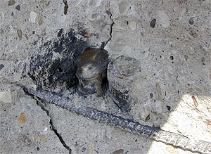 Figure 5. Burn scar on shattered concrete is evidence that lightning found a vertical reinforcing rod (center), which likely acted as an efficient Ufer ground, offering lower resistance than that of the installed grounding/lightning protection system.
“And, keep in mind that the geology and soil characteristics of a site are an important part of evaluating a grounding system. In this case, as in most others we’ve worked with, the soil and hydrology contributed to the high-resistance conditions we encountered.”
Good and Not-so-good Components
Conroy reported that some components of the facility’s original grounding system were adequate, others not:
- The mast itself was grounded by two 8-foot copper-clad rods driven near the tower base. The rods had been bonded to the tower with AWG #2 solid bare copper (Figure 6). Additional runs of #2 copper, also bonded to the electrodes, connected to a few legs of the 100-foot-long ice bridge that connects the tower with the KPTH transmitter building (Figure 7). Still more grounding connections were made to flat-strip copper conductors leading to transformers and nearby equipment (Figure 8). Conroy measured a ground resistance of 190 ohms at the tower base.
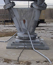 Figure 6. One of two original AWG #2 copper ground leads at the tower base (foreground, bare wire) were augmented by three new 250-kcmil tinned copper conductors (two shown, in protective sleeves).
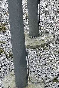 Figure 7. Two original AWG #2 copper grounding conductors were bonded to legs of the ice bridge. These and other existing grounds were retained and bonded to the new and more robust grounding system installed by CPC.
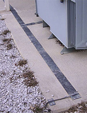 Figure 8. Existing flat-strip copper grounding conductors, used with transformers and other outdoor equipment, were retained and bonded to the new system (large conductor in foreground). The existing outdoor grounding system was also tied into these strips (not shown).
 - Equipment inside the KPTH transmitter building appeared to be properly grounded by way of copper strip conductors and two grounding bus bars from which heavier conductors were fed through walls to the outdoor system (Figure 9). These grounding connections were superimposed on the usual equipment grounds. A similar grounding system had been installed at the KMEG transmitter building; however, the ice bridge to that building was not effectively bonded to the grounding system.
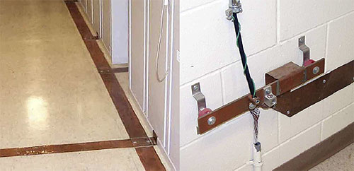 Figure 9. Grounding connections inside the transmitter building used flat-strip copper (left photo) connected via a ground bus (right photo) to the outdoor electrode field.
 - The site was fed from a 13-kV overhead utility circuit that was converted to an underground cable at the property line. The underground cable runs to a primary distribution switch that serves several pad-mounted transformers. The primary switch was grounded with an 8-foot ground rod whose ground resistance measured an uncomfortably high 190 ohms. Each of the tower’s nine anchors was protected by a single 8-foot copper-clad steel rod connected to the guy cables with AWG #2 bare copper. Exothermic welds were used to bond the #2 copper to the electrodes. Connections to the guy cables themselves were made with double U-bolts and tin-plated brass plates (Figure 10).
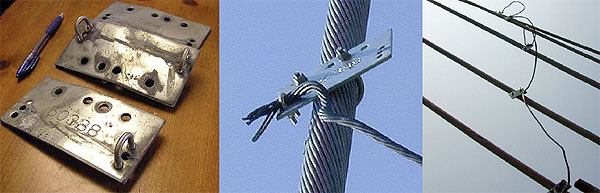 Figure 10. Connections between grounding conductors and guy cables were originally made with tinned-brass double U-bolts (left) that caused the two cables to cross at right angles (center), creating a zigzag orientation. Wind-driven vibration of the guy cables caused the springy U-bolt connections to loosen, thus increasing electrical resistance.
Conroy had misgivings about those connections, since the components were not listed products and the cables were attached at 90° angles to the guy cables. Good practice normally calls for large-radius bends on lightning protection conductors.
Bad Vibrations
“When you work near one of these very tall towers, you’re struck by the noise generated by the wind blowing through the tower lattice and guy cables,” says Conroy. “Grab hold of one of the cables and you can feel the vibration, which is surprisingly strong. It’s that vibration which, over time, can loosen the grounding connections, and that’s exactly what happened here. The loosened connections contributed to the high system resistance we found at those locations.
“Making this situation worse were the U-bolts and tinned-brass plates used to connect the AWG #2 grounding conductors to the guy cables. The plates forced the grounding conductors to cross the cables at right angles at the point of connection, leaving the conductors contorted into a zigzag path from the electrode to the uppermost guy (Figure 10). With lightning conductors, it’s better to keep conductors as straight as practical and to use generous radii when turns are unavoidable.
“Finally, we pulled out and inspected the grounding electrodes at the anchors and found that several of the exothermic welds had failed. Several conductors were also broken, possibly by earthmoving equipment during construction. With all these problems, plus the poor connections and high ground resistance, it’s no wonder lightning ignored this part of the grounding system!”
New Grounding System
Conroy retained some elements of the existing grounding system but augmented it with a new, more robust system. At the tower base, he kept the two original electrodes but added three 80-foot-deep stainless steel electrodes at 120º intervals around the base and between 73 and 80 feet from it (Figure 11). The electrodes were surrounded along their full length by granular bentonite, a clay mineral that absorbs and retains ground moisture readily and, in so doing, swells to make good contact between the electrode and the surrounding earth. Bentonite also maintains good electrical conductivity under those conditions. Stainless steel electrodes and couplers were used here, because of the depth needed to achieve sufficiently low electrical resistance. However, bentonite is especially beneficial with copper-clad steel electrodes, because it buffers pH and creates an electrochemical environment that protects against corrosion in otherwise aggressive groundwater. Grounding Perfection, Inc., of Fremont, Nebraska, installed the deep ground rods using a ground rod driving machine invented by the company’s founder.2
 Figure 11. The new grounding system at the tower base includes three deep-driven stainless steel electrodes linked by a 250-kcmil tinned copper ring ground. The ring connects to the tower base via three 250-kcmil radials.
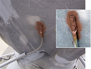 Figure 12. One of three new 250-kcmil tinned-copper grounding electrode conductors installed in 2005. The inset shows the mechanical-type connector bolted to the tower base. Rust-resistant paint coats the connection.
Conroy connected the electrodes with a 250-kcmil tinned-copper ring ground and then ran three 250-kcmil radials from the ring to the tower base. All cable connections were made with tinned, solid-copper mechanical Burndy connectors (Figure 12). Conroy chose tinned-copper for its good corrosion resistance in soils and because it has little tendency to induce dissimilar-metal (galvanic) corrosion when in contact with copper, copper alloys or galvanized steel. Although copper’s high corrosion resistance does not ordinarily require it, Conroy swabbed all mating surfaces with antioxidant compound and coated all connections with corrosion-resistant paint.
The old system’s connections to the tower and ice bridge were retained (Figure 7), but two of the new 250-kcmil radials and the ring ground were also bonded to legs of the ice bridge (Figure 13) and to existing ground straps at outdoor electrical equipment (Figure 8). The old and new systems were then bonded together (Figure 14). Conroy reasoned, “With lightning, you can never have too many electrodes, and it’s always prudent to spread out incoming surges over as broad an area ― and as large a volume of earth ― as possible.”
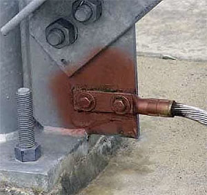 Figure 13. A 250-kcmil tinned-copper grounding conductor connected to an ice bridge leg. The ice bridge connects the tower and the KPTH transmitter building.
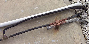 Figure 14. Existing and new grounding conductors at the tower were connected to create as large a system as possible. Here, new 250-kcmil tinned-copper grounding electrode conductors are crimp-bonded to old but still functional AWG #2 bare copper.
Guy Anchor Grounds
In place of the existing 8-foot rods at the guy anchors, Conroy drove 35- to 75-foot-deep stainless steel electrodes (Figure 3), again using bentonite as a backfill agent. He measured ground resistance as the rods were being driven, stopping only when an acceptably low level was attained. The new electrodes were left protruding approximately three feet above grade to facilitate testing and inspection and to prevent cable damage from mowing equipment, as well as corrosion from herbicides, (Figure 15).
From each electrode, he ran 250-kcmil tinned-copper leads to the guy cables, replacing the original double U-bolts shown in Figure 10 with listed, tin-plated silicon-bronze connectors that enabled the grounding conductors to run at a shallow angle with the guys (Figure 16). He also doubled the bronze connectors on the uppermost guy ― the one most likely to see a lightning surge.
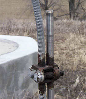 Figure 15. One of nine deep (up to 75 feet) grounding electrodes installed at the tower's guy cable anchors. The stainless steel electrodes were mechanically bonded to 250-kcmil tinned-copper conductors using approved, silicon-bronze mechanical connectors. The brown coating is a corrosion-resistant paint.
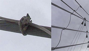 Figure 16. Approved, silicon-bronze connectors enable cables to run parallel at the point of contact, with orientation of the grounding conductors between guys at a narrow angle with the cables. (The pulleys seen at right are part of the cables' sway-damping system.)
At each of the three outermost anchors, Conroy bonded the new deep electrodes to three additional 50-foot long, AWG #2 bare copper leads. These, he buried in 50-foot-long, 120º radially spaced trenches, bonding them to 8-foot electrodes salvaged from the original system. The combined grounding electrode system thus resembles a giant spider web.
Finally, Conroy installed another deep electrode at the utility switch and bonded it to the ground conductor in the 13-kV feeder (Figure 17). This electrode, he reasoned, would provide a low-resistance path for the primary lightning protectors located in the primary switch and would better shunt to ground any high-voltage surges caused by lightning strikes to overhead lines on the nearby grid.
Very Low Ground Resistance = Ongoing Protection
Every one of the 13 new deep-driven electrodes now measures less than 2 ohms. The three electrodes at the base of the tower average 1.32 ohms, which is about 144 times less (a 99.3% reduction) than the original electrodes. By adding in approximately 800 feet of buried 250-kcmil copper and more than 400 feet of buried AWG #2 copper, the overall resistance of the new tower system ground is estimated to be less than 0.5 ohms. That’s a very low value in its own right, but it’s also an outstanding example of what ca
In the case of the KPTH-KMEG tower, the new grounding system has effectively eliminated lightning damage, both to the tower and to ground-based equipment — including the cable anchors. Although there have been numerous strikes over the years since the system was upgraded, none of them has even caused the transmitter to trip.
What does station management think of the new system? Ask Gina Dierks, the stations’ broadcast IT engineer, or Dale Sherbring, their chief engineer at the time. These broadcast pros agree: “We haven’t had any problems with lightning damage since the new system was installed,” says Dierks,” and we certainly haven’t been taken off the air, which means neither of us has had to go to the tower in the middle of the night. That’s always a good thing!”
Sound Advice from a Pro
Speaking from more than a quarter century’s experience, Martin Conroy offers some sound advice for anyone facing the threat of lighting damage:
“The most important thing is to make certain your system’s ground resistance is low enough ― we prefer five ohms or less ― so that the discharge goes where you want it to,” he says.
“Drive the rods deeper if you have to, because deep electrodes will maintain their low resistance during a discharge event. The deeper the electrode, the larger the volume of earth within the sphere of influence. This enables the system to remain closer to earth potential when strikes occur.
“For example, the volume of earth within the sphere of influence3 of one of the original tower base 8-foot ground rods was approximately 2,560 cubic feet. However, when we calculate the volume of earth within the sphere of influence for one of the new 80-foot-deep ground rods, we get a staggering 2,900,000+ cubic feet, which is more than 1,100 times more earth to hold the system at earth potential during lightning discharge.
“Deep-driven rods in combination with heavy copper cabling have proven to be an effective, reliable and durable solution. And don’t skimp on the copper. Use large conductors, not ‘Code Minimum’ sizes. The conductors are really a small portion of the overall cost of the job.
“Install ring grounds and radials if there’s room, and bond all connections properly. In a major lightning strike, you’re potentially dealing with tens of thousands to hundreds of thousands of amps. Copper is cheap insurance compared with the equipment damage that could occur if the system is inadequate. In the case of the KPTH-KMEG tower, another strong hit might have led to very expensive repairs … or worse.”
The Principals
 Martin Conroy is founder and president of Computer Power & Consulting Corp., Omaha, Nebraska. CPC Corp., which has extensive experience with grounding and lightning protection systems, can be contacted at (402) 571-2322, Fax (402) 728-6662.
 Gina Dierks is broadcast IT engineer at KPTH and a sister station located in Omaha. Ms. Dierks can be reached at [email protected].
 Dale Sherbring was chief engineer for KPTH and KPTM.
Footnotes
 Typical lightning discharges can carry from 30 to 50 kA, although intensities exceeding 200 kA are known. Voltage, which depends on the length of the strike, can reach several megavolts.
- Grounding Perfection Inc.
- The formula for volume of earth within the sphere of influence is: V= (5πL3) / 3. See: E&S Grounding Solutions.