Abstract
During mold design, most consideration given to wear in the ejector system is focused on metal-to-metal interfaces. Specifically, attention is paid to the wear between the pins, sleeves, blades, and the bores through which they pass. This research focused on wear that occurred on the metal core during ejection of glass filled plastic parts. This phenomenon has been largely undocumented, and was, in some cases, found to be aggressive. Certain tool steels and copper alloys with hard coatings were shown to be significantly more resistant to this type of wear than others. In addition, product geometry appeared to play a role in the wear process.
Introduction
The study of wear, or tribology predates injection molding. Much attention has been paid over the last century to the wear of metal-to-metal interfaces. Both sliding interfaces such as pistons and cylinder bores and rotating interfaces including bushings and shafts, or anti-friction bearings are well understood. Many of the things learned about sliding and rotating interfaces in metal to metal systems can be applied to the stripping and sliding interface that occurs between the mold and plastics products during the opening and ejection cycle. A mixture of shared experience and common sense stands as the basis for understanding ejection wear. However, one of the major methods for the reduction of wear, lubrication, in most metal to metal systems is largely inappropriate by todays standards of part ejection.
The molder and mold maker are faced with the knowledge that some parts can cause significant wear to the core and cavity faces. This can be especially acute in areas of zero draft and in deeply cored areas, pins to provide holes for threaded fasteners. In a normally cored part, the product tends to shrink onto the core, thus increasing the drag forces applied between the part and the core during ejection. The traditional approach for reducing wear of cores and certain cavity faces, has been twofold. First, the polishing of smooth surfaces tends to decrease the amount of mechanical interlock between the molded part and the molding surface. Second, increased mold surface hardness is a first line defense against wear of the surface. Surface hardness has either been achieved through a change in the type of steel, heat treatment, or by using a hard plating or coating.
Past research work has concluded that between 60% and 80% of all heat that must be given up by a molded part is transferred to the mold core 1. Thus high thermal conductivity materials were shown to be the logical choice for cores and core like structures. However, there has been the general perception that high thermal conductivity materials, specifically copper alloys lack the requisite wear resistance needed for longevity in high wear applications 2. The focus of this research was the resistance of various mold materials to the wear forces applied by the part to the core during ejection. Uncoated copper alloys and standard tool steels were tested along with a variety of hard coatings and platings applied to the copper alloys. Tests were conducted as part of the ongoing long term wear study at Western Michigan University and were coordinated with the evaluation of other aspects of wear during the molding process.
Description of Equipment
The experiment used a geometrically balanced eight-cavity mold with edge gate .76 x .76 mm (.030" x .030") and minimal draft. A DME straight-shot hot sprue bushing was used. The mold had four point guided ejection using bronze plated bushings. Parts were ejected using ion nitrided (Rc 65-74) ejector sleeves at the parting line. Each sleeve had vacuum release hole to aid in part ejection. Die springs and early return pins provided pre-return of the ejector plates and sleeves. Registration of the cavities and cores was assured through the use of four mold side interlocks. The cavity and core retainer plates were made from hardened H13 (Rc54). Both the A and B plates were cooled using ¼ NPT water lines configured in a single circuit around the perimeter of the tool. Four baffles on each side of the tool delivered water to the cavities. A copper chill-plate mounted on the back of the tool provided cooling to the cores. The parts were 1.5 mm (.06") thick round chips, 19 mm (.75") in diameter with a 5 mm (.20") high wall running around their diameter. A flat was formed on the inside of each part by a flat cut into the core pin 2.
The resin used in the study was 33% glass-filled Nylon 6 supplied by Honeywell. This material was chosen as representative of the wear properties seen in most glass filled engineering resins. Prior to molding, the nylon was dried to .02% moisture content. Shots that were not retained were ground by a nine-blade Conair auger-fed grinder with a screen size of 5mm (3/16) for recycling. After grinding, the resin was fed through a cascade aspirator to remove fines. AutoLoad vacuum accelerators were used for resin conveyance.
All molding was conducted with a 77 metric ton (85-ton) VanDorn hydraulic toggle injection molding machine with a 35 mm (1?") diameter screw and a 20.6 cc (5 ounce) maximum shot size. An AEC mold temperature controller regulated mold coolant temperature. Coolant flow rate, input and output temperatures, and pressure loss was monitored in all cooling circuits.
Methodology
Many of the procedures are detailed in previous work 3, 4. The experiment used nineteen base material and plating combinations including three copper alloy base materials, which were tested with and without platings. The platings were electroless nickel (Rc50), titanium nitride (TiN) (Rc84), industrial hard chrome (Rc66-70), Armoloy® TDC densifyed chrome (Rc72), and Armoloy XADC® chrome-diamond nano-composite (Rc90). The copper alloys included C18000 SiNiCrCu (Rb85-96), C17510 BeCu (Rb95-100), and C17200 BeCu (Rc34-40). The thickness of electroplating was .005mm (.0002”) and the electroless coating thickness was .008mm (.0003”). Unplated P20 (Rc32) and hardened H13 (Rc54) were also included as control materials.
Experimental Design and Measurement
 Figure 1. Core showing location of ejection wear.
Dependent variables in this study included the depth of wear measured on the core pin at the parting line (Figure 1), the number of cycles, and visual observations (e.g. scratches, chips, etc.) made at the time of measurement. Independent variables included nineteen treatment combinations developed from the core five substrate materials (base material) and the five platings and coatings. Three generations of resin were used (virgin, first, and second generation regrind).
The experimental design for the study was a randomized design, which included two full replicates of each core/plating material combination. Additional replicates (four to six) were included for uncoated pins (i.e. the three copper base materials and P20). At this writing, not all replicates had reached their endpoint in the study. However, nine combinations (unplated C17200, unplated C17510, unplated C18000, TiN C17200, TiN C17510, TDC C17200, XADC C17200, XADC C18000 and P20) did have two or more replicates completed. It was felt these relatively diverse combinations would provide a reasonable estimate of the within combination variance for a preliminary analysis of the data. It was further decided the treatment effects would be restricted to a more general classification by and uncoated pin material, and coating material (base material ignored), yielding a total of ten treatment groups.
The data were collected under rigorous laboratory conditions. Five to seven samples of the unplated copper alloys and P20 were tested. A custom-build gage provided measurements with a resolution of .00127 mm (.00005). A Nikon Video Measurescope and a WYKO interference microscope were used to collect observational data 3.
Findings
Due to the duration of this study, not all possible hard-coated combinations were evaluated. At this writing, 1.65 million shots at 13g per shot had been run. This yielded approximately 23.5 tons of molding shots or 13.2 million parts. The following data are presented using unplated P20 as the benchmark. The average wear life of those cores made of unplated P20 was considered to be 100% wear. P20 is the standard tool steel used for most injection molds. This was intended to provide a benchmark familiar to molders and mold makers.
Figure 2 illustrates differences among the three unplated coppers and P20. Failure was defined as the first evidence of any scratching or brightening of the parting line interface with the core. Cores reaching failure continued in the experiment to monitor the relative progression of stripping wear. C18000 and C17510 each had eight samples fail, while C17200 and P20 each failed seven samples. This box and whisker plot illustrates the relative uniformity of the median, and 50% range of the three copper alloys. Standard analysis of variance (ANOVA) methods were used to evaluate differences among the treatment. The least squares difference (LSD) procedure was used for post hoc mean separation tests of the treatment groups 5. As seen in Table 1 , the three copper alloys were not significantly different from each other (p>.05) but were shown to be different than P20 (p>.05).
 Figure 2. Relative ejector wear of unplated cores.
| LSD test; variable PERCENT SHOTS-TO-FAILURE Homogeneous Groups, alpha=.05 MAIN EFFECT: BASE |
|||
|---|---|---|---|
| Mean Percent | 1 | 2 | |
| C18000 {1} | 39 | xxxx | |
| C17510 {2} | 41 | xxxx | |
| C17200 {3} | 43 | xxxx | |
| P20 {4} | 100 | xxxx | |
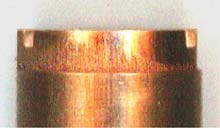 Figure 3. Ejection wear of an unplated core. The .0762 mm (.003) step worn in the core can be seen.
Wear life was defined as the number of injection cycles to first evidence of stripping wear, presumably due to the part shrinking onto the core, and applying hoop stress during ejection. This resulted in a slow progression of undercutting at the parting line. Since this was a round part gated on one side, wear generally ninety degrees in either direction of the gate. Wear proceeded across the core both toward the end of fill and back toward the gate. It was suspected that this was due to the part shrinking to a slightly elliptical shape during cooling due to polymer and fiber orientation around the circumference of the core. Figure 4 illustrates the steady progression of wear as a C17200 core is undercut by successive ejection of parts. This figure illustrates how the step was formed as the core was undercut at the parting line through successive part ejection.
 Figure 4 . Progression of wear as the pin in undercut.
A review of the LSD mean separation results suggested the XADC coating sustained lower wear than all other treatment groups (p<.05). Chrome and TDC also demonstrated lower wear/longer life than many of the other treatments, including P20 (see Table 2). XADC and chrome both demonstrated significantly longer life than H13 (p<.05).
| Treatment | Mean | Member of Groups |
|---|---|---|
| C17510 |
0.4034 |
a |
| C17200 |
0.4314 |
a |
| C18000 |
0.7395 |
a |
| P20 |
1 |
a,b |
| C17200 TiN |
1.0588 |
a,b |
| C17510 E. Nickel |
3.1765 |
a,b,c |
| C17510 Chrome |
3.8824 |
a,b,c |
| C18000 E. Nickel |
4.5882 |
a,b,c |
| C18000 TiN |
6.7059 |
a,b,c |
| C17510 TiN |
8.4706 |
b,c |
| H13 |
15.5294 |
c,d |
| C18000 TDC |
28 |
d,e |
| C17200 TDC |
34.4118 |
e |
| C17510 XADC |
53.3176 |
f |
| C17510 TDC |
56.3529 |
f |
| C18000 Chrome |
56.8235 |
f |
| C17200 XADC |
84.8824 |
g |
| C17200 Chrome |
105.2941 |
h |
| C18000 XADC |
118.8235 |
I |
Results for the various coating/base material combinations may be found in
 Figure 5. Ejection wear life of cores as compared to the average life of P20 (at 100%). Relative resistance of plated and unplated cores to wear caused during part ejection.
The three chrome formulations, taken as a group, outperformed all other hard coatings, unplated coppers and tool steels. The mean life expectancy of a chrome plated copper alloy was roughly 4400% that of the average for unplated P20 (see Figure 5). In fact, chrome platings were so effective at extending the life of the copper alloys that it became economically unfeasible to run multiple replications for this experiment. It was estimated that four and five million additional shots would be required to test the missing combinations of base alloys and hard platings, and with multiple replications of each.
Conclusions
The most striking conclusion drawn from these data was that a well applied chrome plating had the capacity to extend the life of any of the copper alloys an average of 44 times the life of a standard P20 core. Thus, chrome based platings provided the best resistance to the wear that can occur during ejection of a molded part. It should be noted that these tests were conducted under rigerous high shear conditions and the part geometry made the cores susceptible to the part stripping wear phenomenon.
The means and medians were undistinguishable among the three unplated copper alloys. Although there were individual differences among the various mold cores with regard to longevity, the unplated alloys on the whole performed in the same way. It was also noted the unplated copper alloys were more susceptible to this type of wear phenomenon than either P20 or H13.
Because of the nature of this wear phenomenon, it produced a steady undercutting of the core wall. Over time the wear phenomenon caused parts to require greater and greater amounts of ejection force due to the undercut. It eventually led to instability in the cycle, not to mention a degradation of the quality of the core side of the part. In an extreme situation, this wear could yield a thickened wall section of the part toward the parting line. Dependent upon the part geometry, this could change the flow characteristics of the part causing the mold to fill differently.
Therefore, it is recommended that copper cores used to mold filled or reinforced resins be chrome plated to avoid this type of ejection wear phenomenon. This is not to imply that all fillers cause wear, or that all mold cores wear in this way. The key agents of wear in this phenomenon are the geometry of part, abrasive nature of the reinforcement in the resin, and the duration of part production. As stated in previous work, the best plating results should occur with an experienced plater who has a familiarity with copper alloys 4. The plater should also be brought into the mold building process at an appropriate time to both understand and comment on the component design prior to receipt at the plating facility. With these considerations, a correctly plated high thermal conductivity, high strength copper alloy mold core should outlast one of hardened H13.
References
- Engelmann, P., Dawkins, E., Shoemaker, J., Monfore, M. (1997). Improved product quality and cycle times using copper alloy mold cores. Journal of Injection Molding Technology, vol. 1 (1), pp. 18-24.
- Engelmann, P., Hayden, K., Guichelaar P., Dealey, R. & Monfore, M. (2001). Injection mold wear mechanisms and mold design. Plastics Engineering,
vol. 57 (4), pp. 40-46. - Hayden, K., Engelmann, P., Guichelaar P., Dealey, R & Monfore, M. (2001). Resistance to erosive wear by copper alloy mold components. Technical Papers, vol. 47, pp. 981-985, Brookfield, CT: SPE
- Engelmann, P., Hayden, K., Guichelaar P., Monfore, M. & Dealey, R. (2001). Comparison of various hard coatings to protect copper mold components from erosive wear. Technical Papers, vol. 47, pp. 986-990, Brookfield, CT: SPE.
- StatSoft, Inc. (1998). STATISTICA for Windows [Release 5.1 J]. Tulsa, OK.
Acknowledgements
The authors extend their thanks to the Copper Development Association Inc. and its members for support of this research. Performance Alloys & Services Inc., PCS company and Johnson Precision Mold and Engineering constructed mold components. Ampco Metals Inc., BrushWellman Inc., Copper and Brass Sales, and NGK Metals provided mold alloys. Armoloy of Illinois, Hale Chrome Service and Balzers, Inc. provided the platings. Honeywell provided the nylon 6. The WMU Tribology Lab and Dr. Harold Michels of the Copper Development Association Inc provided research assistance.
Each of the following students invested 200-400 hours toward the completion of this research: Kevin Andruszkiewicz, Eric Burgess, Eric Grant, Carlene Harris, Dennis Creedon, Thomas Hall, Leslie Shaw, Gregory Snitgen, Alicia Habercorn, Allen Woodruff, Ryan Brill, Jared Patterson, Troy Winningham, Rich Brothers, Adrian Sultana, Frank Asher, Mike Buckle, Jeff Lewis, Marshall Proulx, Jen Vanover, Leonid Fedorovitch, Keith Wilkenson, Damian Garland, Matt Machala, Ken Smith-Wedel, Mike Westra, Dashia Bowens, Meghann Dickinson, Robert Smith, Jason Worrall, and Deb Wilde.