by C.A. Powell and H.T. Michels; Paper 00627; CORROSION/2000; ©NACE International
- Abstract
- Introduction
- 90-10 and 70-30 Copper-Nickel Alloys
- Corrosion Resistance
- Biofouling Resistance
- Conclusions
- References
ABSTRACT
This review describes the behaviour of the 90-10 and 70-30 copper-nickel alloys, which were developed for and have been used extensively in seawater applications for over half a century. It provides an assessment of the corrosion resisting characteristics and also the inherent biofouling resistance of the alloys with the aim of learning from past experiences and ensuring good commissioning and operational practices for future use.
INTRODUCTION
Copper-nickel alloys were developed specifically for seawater service over five decades ago, initially for condensers and piping systems. Their overall suitability has since been confirmed by continuing use in these and other marine applications. The alloys are currently used in sizeable quantities for offshore, power, and desalination industries and also continue to be used by many Navies and in merchant shipping.
Although developed for seawater corrosion resistance, it was soon recognised that the alloys also had inherent resistance to macrofouling. This property has been advantageous in avoiding or reducing the necessity for biocide dosing in condensers and seawater systems, and in reducing drag forces and cleaning regimes on offshore platforms and boat hulls.
Even as established alloys, knowledge of copper-nickel alloys evolves further as new applications arise, appreciation of corrosion analysis and monitoring progresses, manufacturing techniques change and engineers new to the product provide different perspectives. Occasionally, the lessons learned in earlier times are lost and previously solved problems re-occur.
This review is aimed at providing a current understanding of both the corrosion and biofouling properties of the more common copper-nickel alloys through established and new data, exposure trials and service experience. Good commissioning or initial start-up and operation practices are also reviewed to enable optimum performance in service.
Back to Top90-10 AND 70-30 COPPER-NICKEL ALLOYS
There are two main copper-nickel alloy grades used in marine service which are generally available in most product forms. These are copper base alloys with either 10% or 30% of nickel, and are described as 90-10 and 70-30 copper-nickel respectively. Both alloys contain small but important additions of iron and manganese which have been chosen to provide the best combination of resistance to flowing seawater and overall corrosion resistance. The 30% nickel alloy is stronger and can withstand higher seawater velocities but, for most applications, the 90-10 alloy provides good service at a lower cost and of the two alloys tends to be the one that is more widely used. Their US and European alloy designations are given in Table 1. Also worthy of mention is a modified 30%Ni alloy containing 2%Mn and 2% Fe, which is only commercially available as condenser tubing and is being used particularly in the heat rejection section of multistage flash desalination units where higher resistance to impingement corrosion is required.
| Alloy | UNS No | ISO | CEN |
|---|---|---|---|
| 90Cu-10Ni | C70600 | CuNi10Fe1Mn | CW352H |
| 70Cu-30Ni | C71500 | CuNi30Fe1Mn | CW354H |
Although ranges for elements in the chemical compositions vary between standards, grades of the 90-10 and 70-30 alloys suitable for welding generally fall within the limits given in Table 2. Maximum levels are defined for some specific impurities because of their effects on hot ductility, hot workability, and weldability. These elements can also arise from external contamination and therefore precautions are necessary when the alloys are handled during forming and welding. The 2%Mn and 2%Fe grade is produced as seamless tube for expanding into tube sheets so that welding is not necessary. A companion welding product is not available.
| Alloy | Mass % | ||||||||
|---|---|---|---|---|---|---|---|---|---|
| Cu | Ni | Fe | Mn | Zn. Max | C Max | Pb Max | S Max | Other* Max | |
| 90-10 | Rem. | 9.0-11.0 | 1.0- 2.0 | 0.5- 1.0 | 0.5 | 0.05 | 0.02 | 0.02 | 0.1 |
| 70-30 | Rem. | 29.0-33.0 | 0.4-1.0 | 0.5-1.5 | 0.5 | 0.05 | 0.02 | 0.02 | 0.1 |
| Cu-30Ni 2Mn-2Fe |
Rem. | 29.0-32.0 | 1.5- 2.5 | 1.5- 2.5 | 0.5 | 0.05 | 0.02 | 0.05 | 0.2 |
| * Total other impurities | |||||||||
The 90-10 and 70-30 alloys, however, are readily welded by most common methods (1). Consumables of the 70-30 alloy should be used to weld both alloys. For welding copper-nickel to steel, 65% nickel-copper alloy consumables should be used as they can tolerate more iron dilution from the steel than the 70-30 copper-nickel alloy consumables.
Weld consumable specifications and compositions are shown in Table 3. They contain small titanium additions to counteract atmospheric contamination during welding operations.
| Type | AWS | DIN | Composition - Mass % | ||||
|---|---|---|---|---|---|---|---|
| Cu | Ni | Mn | Ti | Fe | |||
| Covered electrodes | |||||||
| 70Cu-30Ni | A5.6 ECuNi | EL-CuNi30Mn | 67 | 30 | 1.8 | 0.15 | 0.6 |
| 65Ni-30Cu | A5.11 ECuNi-7 | EL-NiCu30Mn | 30 | 63 | 3.5 | 0.2 | 2 |
| Filler wires | |||||||
| 70Cu-30Ni | A5.7 ERCuNi | SG-CuNi30Fe | 67 | 31 | 0.8 | 0.3 | 0.5 |
| 65 Ni-30Cu | A5.14 ERNiCu-7 | SG-NiCu30MnTi | 64 | 29 | 3.2 | 2.2 | <1 |
CORROSION RESISTANCE
The Importance of the Surface Film
The seawater corrosion resistance offered by copper-nickel alloys results from the formation of a thin, adherent, protective surface film which forms naturally and quickly upon exposure to clean seawater. The film is complex and predominantly comprises of cuprous oxide, often containing nickel and iron oxide, cuprous hydroxychloride and cupric oxide (2,3). The film can be brown, greenish brown or brownish black.
Initial exposure to clean seawater is crucial to the long-term performance of copper-nickel. The initial film forms fairly quickly over the first couple of days but takes 2-3 months to fully mature(4). Figure 1 shows the rate of film formation on 90-10 copper nickel in seawater at 16°C measured by copper in the effluent of a condenser over a 3-month period after start up. Copper content was found to decrease to one tenth in ten minutes and one hundredth in an hour. After three months, the copper in the effluent was virtually the same level as that of the intake water. Indirectly, this shows that the maturity of the protective film reduced the corrosion rate of the condenser surface.
 FIGURE 1. Formation rate of corrosion product film on Alloy C70600 in seawater.
At higher temperatures, the film forms and matures faster(5). At 27°C, a common inlet temperature for Middle East desalination plants, rapid film formation and good protection can be expected in a few hours. At lower temperatures the process is slower but the film does form even in Arctic and Antarctic waters.
General Corrosion Rates
Once a good surface film forms, the corrosion rate will continue to decrease over a period of years and to exhibit the classical parabolic growth rate of protective layers. For this reason, it has always been difficult to predict the life of copper-nickel based alloys based on short-term exposures. Normally, corrosion rates of 0.02-0.002 mm/yr are anticipated(6).
Specific corrosion rate measurements at LaQue Corrosion Services(7) taken over fourteen years in tidal, flowing (0.6m/s) and quiet seawater show the corrosion rate decreases over a period of 5-6 years, stabilising out at about 1.3µm/yr, as shown in Figure 2.
 FIGURE 2. The change in corrosion rate with time for 90-10 and 70-30 copper-nickel in quiet, flowing and tidal zone seawater.
The presence of sulfides in polluted water and the decomposition of organic matter may lead to higher corrosion rates and pitting, as will be discussed later.
Localised Corrosion
Copper-nickel alloys also have good inherent resistance to chloride pitting and crevice corrosion. In fact, crevice corrosion seldom occurs and is therefore not well documented. The mechanism is a metal ion concentration cell type(6) and is different to that occurring in stainless steels as any corrosion occurs outside the crevice. Copper ions, which are released by surface reactions within the crevice, are not swept away and concentrate there. The area within the crevice becomes more noble than either the mouth of the crevice or the adjacent exposed region. The resulting corrosion occurs adjacent to the crevice, and tends to be shallow in nature.
Copper-nickel alloys are not susceptible to chloride or sulfide stress corrosion cracking or hydrogen embrittlement, and unlike brasses have not been found to suffer cracking due to ammonia in seawater service. The presence of ammonia may however cause higher corrosion rates. Ammonia may be released as a result of decaying matter on the seawater side of condenser tubes or may be present on the steam-condensate side when certain water treatment chemicals are used. In the latter situation, ammonia concentrations may reach high levels in the air removal sections of condensers. The presence of ammonia can lead to corrosion. However, the 70-30 copper-nickel alloy displays lower corrosion in ammonia than the 90-10 alloy and the rates of both are lower than in those observed in other copper based alloys(8). Copper-nickel tubing is resistant to chlorination at normal dosing levels used to control biofouling. Excessive chlorination, however, can be detrimental.
While dealloying can occur in copper alloys, it is not a common occurrence in copper-nickel alloys. Denickelification or hot spot corrosion has been encountered occasionally in the 70-30 copper-nickel alloy in refinery overhead condenser service, where hydrocarbon streams condense at temperatures above 150°C. This appears to be due to thermo-galvanic effects resulting from the occurrence of local hot spots. The solution has been to remove deposits which lead to the hot spots either by more frequent cleaning or by increasing flow rates(6). Hot spot type corrosion can occur at near ambient temperature seawater if ammonia is present. Again, prevention requires avoidance of slow flow and dead areas; dosing the cooling water with ferrous ions is also advantageous(9).
Velocity Effects
With increasing seawater flow rate, corrosion rates remain low due to the resilience of the protective surface film. Once, however, the velocity for a given geometry exceeds a critical value, at which shear stresses are sufficiently high to strip off the protective corrosion film, damage in the form of impingement attack may occur. General experience has shown that 90-10 and 70-30 copper-nickel alloys can successfully be used in condensers and heat exchangers with velocities up to 2.5m/s and 3m/s respectively. For pipeline systems, higher maximum design seawater velocities of 3.5m/s for 90-10 copper-nickel and 4m/s for 70-30 alloy can safely be used for pipes 100mm in diameter and larger, as described in British Standard BS MA18.(10). Although these values are now considered to be conservative(11), such guidelines have worked well because they take into account normal velocity raisers within piping systems such as bends, which can cause areas of high local flow rates. Nevertheless, extreme turbulence should be avoided. Instances where this may occur include tight radius bends, partial blockages and areas downstream of partially throttled valves. Minimum flow rates of more than 1m/s are usually preferred to avoid sediment build up.
In multistage flash desalination units, the 30%Ni alloy containing 2%Mn and 2% Fe which has higher resistance to impingement than the standard 70-30 alloy is commonly preferred for heat exchanger tubing in the heat rejection section (5,12). The normal design velocity in this section is about 2m/s but local turbulence and high velocities can occur if debris passes through screens or there is unsatisfactory flow conditions in water boxes or unsatisfactory entry conditions into the tubes. This alloy has been found to give very good performance.
The seawater velocities for copper-nickel alloys discussed until now have been for continuous flow situations. Fire-mains can encounter intermittent high velocities of 12-15m/s during test practices as well as during actual fires. Experience has shown that these high flow rates are acceptable for the short term practices used in such applications.
The hydrodynamics of ship hulls are somewhat different than piping systems. Experience to date has shown minimal corrosion after 14 months at 24 knots (12m/s) for the 90-10 alloy(13) whereas the highest recorded velocity is 38 knots (19m/s) for a patrol boat which showed no measurable thickness loss after 200 hours at maximum operating speed(14). The upper service velocity for hulls is still to be established. The velocity capabilities increase upon going from condenser to piping systems and on to ship hulls because of fluid dynamic boundary layer growth.
Sand Erosion
The effect of sand abrasion in seawater has been investigated but is difficult to quantify(6). Sand loadings of less than 200ppm rarely damage good protective films on copper-nickel alloys. Very fine sand (<0.05 mm) loadings are tolerable up to about 1000ppm. Larger diameter sand particles tend to be increasingly abrasive to the film in the 200-1000ppm range. The 70-30 alloys have somewhat greater tolerance for sand. For sand loadings of 1000ppm and for larger particles of sands in the 200-1000ppm range, the 2% manganese, 2% iron, copper-30% nickel alloy, C 71640, has proven very resistant. In fact, the alloy was originally developed to combat sand erosion at Uskmouth Power Station in the UK.
Galvanic Properties
Copper-nickel alloys lie mid-way in the galvanic series being compatible with other copper alloys but more noble than zinc, aluminium, steel and aluminium bronze and less noble than passivated stainless steels, nickel alloys and titanium. The 70-30 alloy is slightly more noble than the 90-10 alloy. As with all bimetallic couples careful attention should be given to avoiding unfavourable galvanic area ratios.
Galvanic contact with less noble copper-alloys, carbon steel and zinc negates the biofouling resistance of copper-nickel. Therefore, in applications requiring the full biofouling resistance of copper-nickel, such as boat hulls, the use of anodes and impressed current cathodic protection systems should be avoided.
Splash zone sheathing on steel offshore platforms in 90-10 copper-nickel should at least span from below mean tide level to well into the atmospheric zone. Potential galvanic corrosion on the adjacent steel is addressed by coating the top section with paint; the bottom, submerged junction will be protected by the cathodic protection system normally applied to the structure(1,15).
On copper-nickel boat hulls, careful attention is required for all hull fittings, and propellers as the hull will not require cathodic protection. Hull fittings should be in copper-nickel or a more slightly noble alloy. This is not only to protect the fittings but also to achieve optimum biofouling resistance of the copper-nickel, as will be discussed later. Nickel aluminium bronze is preferred to manganese bronze for the propeller, since it is the more noble alloy. Corrosion, particularly dezincification is probable if the less noble manganese bronze is used as experience in the first 90-10 copper-nickel hulled boat, the Copper Mariner(16) and more recently in New Zealand on a copper-nickel sheathed vessel(17).
Handling Sulfides
If exposed to polluted water, especially if this is the first service water to come in contact with the alloy surface, any sulfides present can interfere with surface film formation, producing a black film containing cuprous oxide and sulfide. This is not as protective as films formed in clean water and higher general corrosion rates and pitting can be experienced. The sulfide film can gradually be replaced by an oxide film during subsequent exposure(18) to aerated conditions, although high corrosion rates can be expected in the interim. However, if an established cuprous oxide film is already present, then periodic exposure to polluted water can be tolerated without damage to the film.
Sulfides are present in polluted water either as industrial effluent or when the water conditions support the growth of sulfate reducing bacteria. They can also occur in stagnant conditions as a result of decomposition of organic matter. Exposure to sulfides should be restricted wherever possible and particularly during the first few months of contact with seawater while the oxide film is maturing.
 FIGURE 3. Influence of sulfide and oxygen on the corrosion current in a copper-nickel alloy exposed to flowing seawater.
Figure 3(18) examines the behaviour of 90-10 copper nickel in aerated and sulfide polluted waters. In the complete absence of oxygen, corrosion rates are low as indicated by point 1 and current i1 and remained low up to sulfide concentrations as high as 55g/m(3) and velocities of 5m/s. In aerated waters, corrosion rates are somewhat higher, referring to the line AB and current i2. The higher corrosion rate in aerated waters is due to the change from hydrogen reduction to oxygen reduction as the primary cathodic reaction. In polluted waters where both oxygen and sulfide may be present under transient conditions, the cathodic reaction is still oxygen reduction with a much higher corrosion rate, referring to point 2 and current i4. This work illustrates the high corrosion rates are likely to occur in partially deaerated waters with sulfides present and in estuarine waters where there is alternate exposure to aerated waters and partially de-aerated waters with each tide change.
For condenser systems, it is the fitting out and commissioning period when problems are most likely to occur from sulfides . The ideal situation whether in a ship or power plant is to recirculate aerated, clean seawater at initial start up for sufficient time to form a good protective film(4,19,20). When formed, this provides a high degree of corrosion protection to subsequent sulfides. In situations where it is not possible to use clean seawater, circulating the system initially with fresh water containing ferrous sulfate additive will encourage effective film formation.
When outfitting in sulfide polluted waters, piping and condensers should be hydrotested with local fresh waters if possible. If hydrotesting must be done in polluted waters, it should be scheduled as late in construction and outfitting as possible. The hydrotest water should be drained after hydrotesting if possible to minimize sulfide attack or the use of ferrous sulfate or other inhibitors can be considered if draining is impractical. The system should be placed in service in clean water as soon as possible.
If polluted seawater is introduced at start up in condensers, it is important to keep it circulating. The system should be drained and air blown dry for standby periods of 3-4 days or more. A similar situation exists at shutdowns.
For other situations where there is brief exposure to sulfides during normal operating service, clean water should be returned to as soon as possible. Normal harbour turn around times which often involve exposure to polluted water have rarely led to significant problems. However, it is beneficial for a flow through the condenser to be maintained, even if necessary at a reduced level, when in port.
In situations where the metal surface becomes exposed to sulfides under deposits or sediment caused by sulfate reducing bacteria e.g. where deposits are not removed from tubing, the remedy is proper scheduled cleaning. Such cleaning is often scheduled at 2-6 month intervals and accomplished by water flushing or cleaning with non-metallic brushes. Alternatively, sponge ball cleaning is also employed. Such procedures are also necessary to restore optimum heat transfer. Where there is long term exposure to deaerated sulfide containing seawater or regular alternating exposure to sulfide polluted water and aerated waters, copper-nickel is generally not recommended.
Ferrous Sulfate Treatment
Ferrous sulfate treatments are not absolutely essential to the successful performance of copper-nickel but can be viewed as a remedy when trouble has occurred or as a precaution if trouble is likely. Most ships in service have operated successfully without any ferrous sulfate dosing.
Ferrous sulfate treatment(20,21) has been found to suppress corrosion rates of copper-nickel in seawater in both polluted and unpolluted conditions. For commissioning which can last from a few weeks to 3 months, the ferrous sulfate content of the cooling water can be set up to 2 to 3 ppm(20). As an alternative method to encourage good initial film formation during commissioning, a system can be, at first, filled with fresh water containing 5ppm ferrous sulfate and left in the system for 1 day. After this initial treatment, ferrous sulfate (5 ppm concentration) should be added to the system and recirculated for 1 hour per day throughout the fitting out period. This practice is also useful when systems are either retubed or renewed (20). During normal service on ships, additional ferrous sulfate dosing is seldom required. Although if exposure to known polluted water is going to occur (e.g. when entering port) a reasonable additional precaution would be to add 5ppm ferrous sulfate for one hour per day during the three days prior to entering while in and after leaving port. One treatment a week can be applied throughout prolonged voyages.
Chlorination treatment and ferrous sulfate treatment should not be carried out simultaneously because chlorine reacts with ferrous sulfate to form ferric sulfate. Since ferrous sulfate is consumed, it is not available to contribute to the development of protective films. The remaining ferric sulfate provides no beneficial effect. An alternative method of releasing ferrous ions into the system is by fitting iron anodes. This however, is more suited to maintaining a protective layer than initial oxide film formation and will also reduce the biofouling resistance as will be explained in the next section.
Other pretreatment chemicals have been studied(22) or used(23) with variable success. Dimethyldithiocarbomate has been used by the British Navy(23) as well as that of Germany.
BIOFOULING RESISTANCE
Copper-nickel alloys have a high inherent resistance to macrofouling. This reduces the frequency of cleaning of piping systems and condensers, and decreases wave loading and fouling removal costs for platform structures. Also, the down time and expense of applying antifouling coatings to boat hulls is avoided and fuel consumption is improved. Fouling that does form is poorly adherent and thus easily removed. The biofouling resistance of copper-nickel tubing allows shipboard condensers to maintain good heat transfer capability for several months between mechanical cleanings without the need for onboard chlorine generators required for other tubing materials.
The most important requirement for optimum biofouling resistance is that the alloy should be freely exposed or electrically insulated from less noble alloys or free of cathodic protection as shown in Figure 4 (6,24).
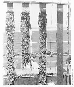 FIGURE 4. Exposure Panels. Panels after 12 months exposure at Langstone Harbour, UK. Left to right: Steel, 90-10 Copper-Nickel Sheathed Steel, Copper-Nickel; all products with aluminum anodes. Far right: unprotected copper nickel. There is no fouling on the unprotected Copper-Nickel.
General observations have led to the understanding that for open seawater exposures, such as experienced on ship hulls or offshore splash zone sheathing, the slime layers (microfouling) do not build up sufficiently to support macrofouling. When exposed to long periods under quiet conditions, some macrofouling will eventually occur but this has been observed to slough away at intervals.
It is generally thought that the 70-30 copper-nickel alloy has less biofouling resistance than the 90-10 alloy, having a lower copper content, but this is not always borne out in practice. The longest running copper-nickel yacht, the Asperida has given trouble free service since 1968 and it has a 70-30 hull. Fourteen year exposure for 70-30 test panels under quiet, tidal and flowing conditions at the LaQue Corrosion Services, Wrightsville Beach, North Carolina, showed negligible fouling after that time(7). Five year exposure data under quiet conditions, again at the Wrightsville Beach site, showed the response to fouling to be the same whether the alloy exposed was 90-10, 70-30 and unalloyed copper itself(3). The copper-nickels in the same trials were found to corrode at one third of the rate of the copper. 70-30 copper-nickel welds occasionally prove preferential sites for fouling compared with the 90-10 base material. However, the welds are slightly more noble than the 90-10 and there may be a galvanic influence on the biofouling resistance of the welds. More detailed examinations are required to explain this. Currently, it suffices to say that any differences in biofouling properties of 90-10 and 70-30 alloys would appear to be of little practical significance for hulls and offshore platform splash zone sheathing.
Ease of Biofouling Removal
In several inspections of the first 90-10 copper-nickel hull, the Copper Mariner, the majority of biofouling attachments have been dislodged apparently during the 3-8 knot travel to and from shrimping grounds(16) and any remaining could be flicked off with a thumbnail. The attachment when it does occur is very light compared to the manner in which barnacles embed themselves onto steel, titanium and other materials without significant biofouling resistance. This has also been confirmed from more recent trials at Langstone Harbour, UK, by IMI Yorkshire Alloys Ltd, which not only showed the ease that the fouling could be wiped away but also the ease with which fouling could be removed compared with steel even when cathodic protection was applied and a sizeable fouling build up had occurred on the test panels6. The latter has also been observed by divers in the Morecambe Field when cleaning legs which have been sheathed with 90-10 copper-nickel for splash zone corrosion protection. The Morecambe Field is a major gas field in the Irish Sea. In 1984, copper-nickel was used to cover legs on production and accommodation platforms, three drill platforms and a flare stack. The sheathing was welded directly to the steel and spanned +13m above Lowest Astronomical Tide (LAT) to -2m below LAT. The sheathing was 4mm thick annealed sheet. The legs were cathodically protected which allowed fouling of the 90-10 copper-nickel(25).
Reasons for Biofouling Resistance
Early theories were linked with the fact that resistance to biofouling was significantly reduced when cathodic protection was applied. These were based on the reasoning that it was copper ions released into the seawater which were toxic to macrofouling. However, copper-nickels corrode at a lower rate than copper and still exhibit a similar biofouling response. Also, long-term trials in support of the Morecambe Field platforms have shown that although biofouling will occur when cathodic protection is applied, some biofouling resistance is retained(26). Table 4 shows data from 10 year trials on sheathed pilings, which were exposed in a natural seawater channel at the LaQue Corrosion Services, in Wrightsville Beach, North Carolina.
| Piling | Kg/sq.m | Percent |
|---|---|---|
| Bare Steel. (control) - not sheathed | ||
| 5 Year removal | 18.00 | 100.0 |
| 10 year removal | 12.00 | 100.0 |
| Concrete Insulated Sheathing | ||
| 5 Year removal | 0.36 | 1.9 |
| 10 year removal | 0.14 | 1.2 |
| Sheathing Directly Welded to Piling | ||
| 5 Year removal | 7.95 | 44.3 |
| 10 year removal | 4.43 | 36.8 |
| Sheathing Directly Welded to Piling | ||
| 5 Year removal | 7.95 | 44.3 |
| 10 year removal | 4.43 | 36.8 |
| Rubber Insulated Sheathing | ||
| 5 Year removal | 0.26 | 1.4 |
| 10 year removal | 0.62 | 5.3 |
The biofouling mass accumulated on the bare steel piling is more than twice as great as that on direct welded copper-nickel, whether or not it was cathodically protected, and more than 20 times that attached to insulated sheathing. On the sheathing in the Morecambe Field itself, the divers estimated the fouling to be reduced to about 30% of the lower adjacent steel.
It was in the 1970's that observations at Wrightsville Beach suggested the surface film itself was largely responsible for the biofouling resistance and that when freely corroding and under quiet conditions, the oxide film would gradually convert to cupric hydroxychloride(3). This film was considered to be less adherent and protective than the cuprous oxide type and would allow fouling to become established. Being less adherent, after a time it would slough away leaving a protective cuprous oxide film exposed again. The observations did not identify any unfouled areas directly adjacent to copper-nickel boundaries which would indicate a copper ion release mechanism. However, since that time, other products have been developed for protecting offshore structures which are composites of copper-nickel wire or granules embedded into an insulating substrate such as rubber or polyester gel with discrete areas of copper-nickel exposed on the surface. These products have shown full protection of the surface although they only expose about 30% of the surface area as copper-nickel(25). Thus, there must be some antifouling effects in close proximity to copper-nickel.
It appears, therefore, that the most likely explanation is that the biofouling resistance is a combination of the two effects; that biofouling response relies on both ion release and the nature of the surface film. It is most probable that it is due to the unoxidised copper ions normally present within the protective film and is an area where more detailed work is required.
Boat Hull Experience
The biofouling properties have been confirmed by evaluating more recent boat hull experience. The benefits of copper-nickel alloys in maintaining a smooth hull surface have been obtained by a number of boat building methods(27).
- Construction of the hull from copper-nickel alloy plate
- Construction of the hull from roll-bonded plate
- Cladding a steel hull with copper-nickel alloy sheet or foil
The Pretty Penny is a 10m yacht built in 1979 made of 3mm 90-10 copper-nickel plate and moored for the greater part of its life in the Thames Estuary on the east coast of the UK. The hull remained clean for the first 3 years, but did exhibit some fouling from mainly grasses and some barnacles in later years, particularly 150-300mm below the water line. This fouling was easily removed manually by a light scraping action while still in the water once or twice a year.
The Italian Ministry of the Interior commissioned 4 fire boats with 90-10 copper-nickel roll-bonded clad steel for the submerged parts of the hulls in 1983. The operators of the fire boats were contacted in 1992 by the Nickel Development Institute to find out their performance. No signs of corrosion were evident on any of the boats. Two, however, had shown some signs of fouling having spent a greater part of their lives in closed, stagnant moorings. A third was moored in polluted water showing no signs of biological activity. The fourth boat moored in freely flowing water showed excellent biofouling and corrosion resistance.
A pilot boat was constructed from clad plate for the Board of Navigation, Finland in 1987. It was intended that the properties of 90-10 copper-nickel should be compared with austenitic stainless steel for use in the Baltic where ice is anticipated. Information in 1994 from Hanko Pilot Station where the pilot boat was located indicated that the vessel was giving good service and the copper-nickel had not been damaged by the ice. The hull had stayed free from fouling with the propeller and the steel front keel being the only places where some mussels had been observed. The welded seams of the copper-nickel sheets were in good condition too.
The Cupro, a small experimental ship with a 90-10 copper-nickel clad steel hull operated in open waters near docks in Japan; operation time was very low to encourage fouling. Over two years during the evaluation trial, the vessel performed well with minimal corrosion. A very low level of barnacle encrustation was found which was not enough to interfere with the operation of the ship and could be easily removed by hand.
To assess the viability of welded sheathing, sea trials were carried out initially by sheathing the complete rudder of a 24 knot roll-on/roll-off vessel called the Great Land operating between Washington and Alaska(13) with 90-10 copper-nickel. Although the rudder was subject to turbulent flow and exposed to conditions where ice and silt were present in the seawater, the copper-nickel was found to be very durable.
A second hull panel trial was on a 16 knot crude oil tanker, the Arco Texas assessing attachment methods and evaluating service performance. Twelve large 90-10 copper-nickel panels were divided into sets of three such that exposure covered fully submerged, alternate wet/dry and splash zone conditions. After two years and seven trips through the Panama Canal, the panels were still intact even though they had experienced several forceful impacts on the sides of the water-way and several had severe scratches. The maximum corrosion rate was measured at 0.013mm/yr and no evidence of fouling was found on the copper-nickel even though it was present on the rest of the steel hull. At the end of the two years, the conventionally coated steel hull had a roughness of 250µm, whereas the corresponding roughness of the copper-nickel was only 53µm. In comparison, the roughness of the copper-nickel rudder after 14 months on the Great Land was consistently lower than 20m, compared with the painted steel hull which averaged 210µm.
The sheathing of a ship's hull with 90-10 copper-nickel foil has involved the application of adhesive-backed panels (approximately 210mm x 500mm) to the prepared hull, allowing about 15mm overlap. The copper-nickel foil thickness chosen is about 0.15mm thick. The panels are easily cut and manipulated even over the most difficult of contours(17).
The bonding system acts as an insulator, and as a barrier to seawater which further protects the hull from the detrimental actions of seawater. An advantage of the system has been that if impact occurs and some panels are damaged, it takes only a short time to repair the sheathing. The system can be applied to hulls on new vessels and as a retrofit.
An evaluation programme on the performance of the foil sheathing commenced in August1993 with two commercial passenger ferries, the MV Koru and the MV Osprey; both of which are in-service around Auckland Harbour, New Zealand(17). One vessel is a slow ferry (10 knots), constructed of fibreglass reinforced polymer, which was retro-fitted with copper-nickel sheathing in 1993. The other vessel is a fast catamaran ferry (22 knots) with a FRP hull, which was sheathed during construction in 1994. The older monohull vessel, MV Koru, was kept in reserve most of the time, whereas the catamaran, MV Osprey, has been in service for about 30,000 nautical miles since construction.
In addition, test programmes involving trials on immersed test panels, commenced over the same time (1993-1999) in Auckland Harbour, Singapore, and Langstone Harbour, UK. The overall trials have confirmed earlier observations about the biofouling properties of copper-nickel but added to the overall experience.
The biofouling resistance is in line with documented accounts such that slime (microfouling) does occur on copper-nickel but colonisiation of macrofoulers is restricted. If colonisation does eventually occur, it can readily be removed by a wipe or finger pressure, such that a light waterblast will quickly remove any growth. The turnaround time for cleaning the MV Koru on the slip by this method is about 1.5 hours. Removal of fouling from the equivalent painted vessels in the fleet can take up to one day of unproductive time per vessel.
The experience on MV Koru and the MV Osprey showed that green algae (slime) formed predominantly on the copper-nickel foil at, or just below the waterline on both vessels. In addition more algae were observed on one side of the MV Koru hull which was facing the sun during out-of-service time. Clearly, sunlight affects the rate of growth of the green fouling (photosynthesis), but the higher temperature of the surface seawater on sunny days may also be a factor.
The green algae were easily removed using rotary brushing underwater, but the growth became firmly attached and more difficult to remove if it dried when the vessel was on the slip-way. It was also observed that small, lightly attached barnacles, grew adjacent to the waterline on the foil when the MV Koru was left moored and unused in the harbour for longer periods of time.
Seawater velocity also had a substantial effect on the degree of fouling resistance of the copper-nickel foil. Areas of the MV Koru and MV Osprey hulls were almost entirely free of biofouling where the velocity of seawater experienced by the alloy exceeded some undetermined speed. Typically, the stern and waterline tended to show earlier signs of fouling than other hull areas.
The effect of water velocity can possibly be related to the sloughing of microfouling from the hull surface. Macrofouling on the hulls of both vessels only resulted after microfouling had been well established on the foil during quiet periods.
Offshore Sheathing
Sheathing offshore in copper-nickel is applied either for splash zone corrosion protection or biofouling and splash zone protection on legs and/or risers(25). For straight splash zone corrosion protection, the copper -nickel is usually welded into position as for the Morecambe Field. For biofouling protection it is supplied as a composite product of half cylinder sheets, perforated sheet, granules or wire onto an insulating backing, e.g.neoprene.
One product, which has been successfully used for splash zone protection of structural legs, cross bracings and riser pipes, involves discrete granules of copper-nickel, 1mm diameter and 1mm long bonded into the surface layer of 3mm thick neoprene sheet. The processing ensures that the granules are distributed and exposed over the surface such that about 30% of the surface is copper-nickel and each granule is close enough to its neighbour to allow complete surface protection(25,28).
Sheets of the composite are press cured and can be then cut to the required sizes, slit to strip, or even rejoined to form continuous tapes up to 50m long. The product can be hot bonded onto elastomeric corrosion coatings or cold bonded directly onto steel. The track record dates back to 1984 with 13,000 square metres supplied for several platforms world-wide.
Antifouling subsea markers(25,29) using copper-nickel are attached to pipelines and underwater areas for offshore platforms and other marine structures. They are used for identification purposes and to guide divers around structures and along pipelines. Fouling resistance is achieved by a surface layer of fine interwoven copper-nickel wire mesh embedded into a bright yellow, pigmented polyester gel. By altering the pigment of the polyester gel for numbers and letters, identification can be readily seen. The copper-nickel layer is insulated from the metal substrate by a fibreglass, polyurethane or rubber backing and the markers can be bonded, strapped, bolted or clipped into position. Currently, the longest known exposure for the markers is 15 years.
CONCLUSIONS
In reviewing the corrosion and biofouling properties of 90-10 and 70-30 copper-nickels in sea water, the alloys are found to possess good resistance. It is also apparent that the following requirements are necessary to achieve optimum service lives:
- Obtain copper-nickel to international standards.
- Use 70-30 copper-nickel consumables for similar welds in 90-10 and 70-30 copper-nickel
- Use 65% nickel-copper consumables for copper-nickel to steel dissimilar welds.
- Heed maximum velocity limits for the alloys.
- Avoid velocity raisers e.g. sharp angled bends in pipe systems.
- During commissioning do not use polluted water.
- Add ferrous sulfate to enhance the protective film formation if extra caution is required.
- To get the best biofouling resistance, insulate copper-nickel alloys from less noble alloys.
References
- A Review of Materials and Corrosion in Desalination-Key Factors for Plant Reliability, Oldfield, J. W., & Todd, B., , IDA World Congress on Desalination and Water Sciences, Abu Dhabi, UAECF, International Desalination Association, .
- Avonclad-a Flexible Neoprene/Copper-Nickel Material for Long Term Antifouling; A Review of Manufacturing, Tests and Recent Installations, Brockbank, J. W., pp 101-103, , London, Paper from Marine Engineering With Copper-Nickel, Institue of Metals Conference Proceedings .
- Behaviour of 90-10 cupronickel in sea water, Parvizi, M. S., Aladjem, A., & Castle, J. E., International Materials Reviews, Vol. 33, 4, pp 169-200, , .
- CA 706 Copper Nickel Alloy Hulls: The Copper Mariners Experience and Economics, Manzolillo, J. L., E. W. Thiele, and A. H. Tuthill, Trans. Soc. Naval Architects and Marine Engineers Journal, pp 22, , .
- Controlling Biofouling on Ferry Hulls with Copper Nickel, Boulton, L. H., C. A. Powell, and W. B. Hudson, Additional Papers, pp 73-87, , 10th International Congress on Marine Corrosion and Fouling, University of Melbourne, DSTO General Document DSTO-GD-0287. Defence Science & Technology Organisation, Australia .
- Copper-Nickel Alloys for the Construction of Ship and Boat Hulls, Glover, T. J., British Corrosion Journal, Vol. 17, 4, pp 155-158, , .
- Copper-Nickel Alloys Resistance to Corrosion and Biofouling, Powell, C. A. and Michels, H. T., Seminar Technical Report, 7044-1919, , Corrosion 2000, NACE, Original title: The Application of Copper Nickel Alloys in Marine Systems .
- Copper-Nickel Composite for Long Term Antifouling; A Review of Recent Applications, K. Miller, , London, Institute of Metals, Proceedings of Marine Engineering with Copper-Nickel .
- Copper-Nickel Sheathing Costing Study-Phase 3, , US Department of Transport, MA-RD Report- 770- 87026 .
- Copper-nickel Welding and Fabrication, Published by CDA Inc as A7020-99/13, Nickel Institute as 12014 Second Edition and CDA UK as Publication 139 Second Edition .
- Corrosion and Biofouling Protection of Ship Hulls Using Copper-Nickel, Powell, C. A, , International Conference on Marine Corrosion Prevention: A Re-Appraisal for the Next Decade, London, .
- Evaluation of Critical Seawater Hydrodynamic Effects of Erosion-Corrosion of CuNi, Kirk, W. W., , ICA, Contractor Report Technology for the Copper Industry: Final Report INCRA Project No. 396 .
- Experience with Copper Alloy Tubing, Waterboxes and Piping in MSF Desalination Plants, Tuthill, B. Todd, J. Oldfield, Vol. III, Paper No 73, pp 251, , IDA World Congress on Desalination and Water Reuse, Madrid, International Desalination Association (IDA); Cencro de Estudios y Expertmerocion de Obras Pubiicas (CEDEX); Ministerio de Medio Ambiente; Ministerio de Formento; Madrid, Spain. .
- Fabrication of Copper-Nickel Alloys for Offshore Applications, Jordan, D. E. and Powell, C. A., , International Conference on Welding in Maritime Engineering, Croatian, Croatian Welding Society, .
- Guidelines for the Use of Copper Alloys in Seawater, Tuthill, Arthur H., Materials Performance, Vol. 26, 9, pp 12-22, , CDA Inc Publication 788/8 and Nickel Institute Publication12003 .
- Heat Exchangers and Piping Systems from Copper Alloys - Commissioning, Operating and Shutdown, M. Jasner, M. Hecht and W. Beckman, , KME, .
- Hot Spot Corrosion in Condenser Tubes: Its Causes and Prevention, Francis, R., British Corrosion Journal, Vol. 22, 3, pp 199-201, , Institute of Materials, .
- Inhibition of Sulfide-Induced Corrosion of Copper-Nickel Alloys with Ferrous Sulfate, Hack, H. P. and J. P. Gudas, , Paper 23 Presented at the International Corrosion Forum Devoted Exclusively to the Protection and Performance of Materials, Houston, Texas. Sponsored by NACE .
- Metallic Coatings for Corrosion Control of Marine Structures, Peters, D. T., Michels, H.T. and Powell, C.A., pp 9-11, , International Workshop on Corrosion Control for Marine Structures and Pipelines, Galveston, TX, American Bureau of Shipping, .
- Non-Ferrous Seawater Systems Using Copper-Nickel Alloys and Cast Bronzes, Todd, B. and Lovett, P. A., Marine Engineering Practices, Vol. 1, Part 10, London, Institute of Marine Engineers, ISBN: 900976 49 7, .
- Pre-Treatment of Condenser Tubing for Enhanced Corrosion Resistance, Lee, T. S., , INCRA Project 284 Final Report .
- Preventing Biofouling with Copper Nickel, CDA Publication, 157, .
- Protection of Seawater System Pipework and Heat Exchanger Tubes in HM Surface Ships and Submarines in Sea Water Systems, Standard 02-781 Issue 2, , UK Ministry of Defence, Not available online but inquiries can be sent to the DStan Helpdesk at [email protected] .
- Salt Water Piping Systems in Ships, British Standard BS MA 18, , ISBN: 0580078337, .
- Sea water Corrosion Resistance of 70-10 and 70-30 Copper nickel-14 year Exposures, Efird, K. D. and D. B. Anderson, Materials Performance, Vol. 14, 11, pp 37-40, , .
- Sulfide Attack in Steam Surface Condensers, Syrett, B. C., pp 3-14, , Blacksburg, Virginia, Virginia Polytechnic Institute, Proceedings of Second Int. Conf. On Environmental Degradation of Engineering Materials in an Aggressive Environment .
- The Interrelation of Corrosion and Fouling of Metals in Seawater, Efird, K. D., Materials Performance, Vol. 15, 4, pp 16-25, , .
- The Resistance of Copper -- Nickel Alloys to Ammonia Corrosion in Simulated Steam Condenser Environments, Caruso,L; Michels, H.T., Materials Performance, Vol. 20, 1, pp 35-39, , NACE International, Proceedings of the American Power Conference .
- Thirteen Year Results of Long-Term Copper-Nickel Sheathed Piling Studies, Pikul, S. J. and B. S. Phull, , Annual Report, ICA Project No. 358 .