![]() Download PDF Version [4.5Mb]
Download PDF Version [4.5Mb]
The Jackson Township, Ohio safety center was completed in 2004. Because its electrical grounding system was incorrectly designed and improperly installed, lightning strikes to the antenna tower (visible in the background) frequently left fire and police services without emergency dispatch capability.
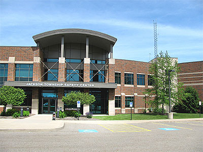
There are 37 Jackson Townships in Ohio, but the Jackson under discussion is in Stark County, between Canton and Massillon. This Jackson Twp. suffered expensive and potentially life-threatening problems with lightning. The reason: an inadequate grounding system.
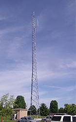 Figure 1. Jackson Township’s fire and police communications equipment is housed in the small remote communications building to the left of the 140-ft antenna tower. The tower has attracted many lightning strikes, and because it was poorly grounded, lightning energy was able to damage equipment in the building and elsewhere on the municipal campus.
Jackson Township is a pleasant, suburban town with parks, shopping centers and the sort of public infrastructure you’d expect for a community of some 38,000 inhabitants. Its fire and public safety departments are well-equipped with state-of-the-art communications gear, but communications was unfortunately one of the things that lightning repeatedly struck.
Troubles began soon after the township completed the Safety Center shown in the above photo. The center is part of a municipal campus of offices, garages, maintenance shops and storage facilities, plus emergency and dispatch communications service facilities for the township and several surrounding communities. Communications equipment is mainly housed in a small transmitter building (referred to as the remote communications building) next to the main antenna tower (Figure 1).
Richard Heck was Jackson Township’s fire chief at the time. His overriding concern was over the interruptions in emergency communications, which are obviously vital in a suburban community. “The damage happened several times over four years,” he later recalled. “In one incident, lightning took out our regional communications center for several hours. That affected 43,000 area residents, not to mention up to 100,000 people who visit for business or shopping. Fortunately, we didn’t have any delayed responses and there were no injuries, but there was a big potential for disaster.”
Expensive Damage
And then there was the cost. Ask Carles Moore, who was Jackson Township’s Central Maintenance Director when this article was prepared. Communications equipment, including the tower, was his responsibility. He could see the tower from his office, and he would tell you, quite emphatically, that “We’ve got a 140-foot lightning rod sitting in our backyard!” Sure enough, in 2004, 2005, 2007 and 2008, Mr. Moore’s lightning rod did exactly what lightning rods do: it directed thousands of amps of energy to earth. But because of the tower’s inadequate and improperly installed grounding system, a portion of the energy destroyed whatever electrical equipment it encountered along the way:
- In August, 2004, a bolt destroyed communication circuit boards, a few surveillance cameras and some computer records. Cost to repair: $4,632.98.
- Repairs for the July, 2005 strike came to $22,959. The tower, radios, telephones, surveillance cameras, the emergency generator, a dictation system and computers took the hit. Technicians returned some essential communications to service several hours later. Complete repairs took five months.
- The most expensive strike, on June 22, 2007, damaged the tower, the emergency generator, surveillance cameras, safety center gate and its access controls. It also took out radio communications for the neighboring towns of Lawrence and Brewster, plus 14 telephones, a fire alarm panel and a router that serves police cruisers. It damaged equipment throughout the municipal campus, including the safety center's gate, transmitter building and transportation maintenance offices.
- Another strike one week later hit a roof-mounted lightning arrestor on the safety center (which didn’t do its job for reasons explained below), resulting in damage to a fire-truck traffic light and, once again, the emergency generator. Together with the earlier strike, the repair cost came to $102,832.
That last expense got the insurance company’s attention. An electrical contractor had begun work during the week between incidents. He repaired some damage but apparently hadn’t done anything to avoid the next calamity. It was time for a second opinion.
Which is precisely what Mr. Moore got when he brought in Tim Cookson of PowerEdge Technologies, a nationally-recognized engineering services firm based in Canton. The company specializes in power quality improvement — and lightning damage is definitely a power quality issue.
Cookson began by evaluating the Safety Center’s electrical grounding system. He identified 14 areas of concern, many of which involved incorrectly positioned, improperly used or non-compliant lugs and connections. He also found serious discrepancies based on poor design or improper installation. Here are a few examples:
-
Two parallel grounding conductors were found connected between one painted utility meter cabinet and the main wireway in the safety building (Figure 2). Aside from the incorrect and non-compliant connection, the 100-ft-long conductors could function as antennae for induced currents or stray RF and thereby inject electrical noise into the grounding system.
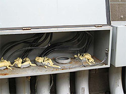 Figure 2. A pair of grounding conductors (front right) improperly connected to a utility meter cabinet. The cables ran 100 ft to the main wireway inside the safety center, and their length invited stray current pick-up by the grounding system.
 - At 16.9 ohms, the ground resistance of the safety center’s grounding system was somewhat high. The IEEE’s “Green Book” (IEEE Std. 192) suggests a maximum of five ohms when computers and sensitive equipment are involved. More important, testing showed the presence of ground loops at all lightning system electrical conductors passing into the remote communications building. Further, Cookson was unable to verify the presence of an electrode array (site drawings called for three electrodes). Further, electrode connections must be accessible for service; these weren’t.
- Water line connections weren’t jumpered across flanges, and the termination point of the grounding conductor at the water line was made between two flanges on the street side of the line using an improvised connection (Figure 3).
- Current on the grounding conductor at the service entrance measured 7.6 A. Among the several likely sources was a non-compliant ground-neutral bond at the emergency generator (Figure 4). The transfer switches for the generator are three-pole, therefore the generator is not a separately derived source and doesn’t require a neutral-ground connection. With the existing bond, any current on the neutral conductor would enter the grounding system, where it could affect sensitive equipment.
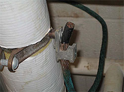 Figure 3. An improper grounding connection between two flanges on the street side of the water line. Flanges were also missing jumpers to provide a path to earth.
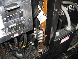 Figure 4. The neutral-ground connection (bottom center) at the emergency generator constitutes a short condition because the transfer switch is three-pole, meaning that the generator is not a separately derived source. The improper connection can inject current into the grounding system.
 - The building steel grounding connection consisted of a non-compliant bar-tap bolted to a painted steel beam (Figure 5). That’s an obvious high-resistance connection. Two such connections were found inside the fire station garage, yet neither column was connected to earth. Down-conductors should preferably be grounded to driven electrodes outside the building. Since the columns weren’t earthed, lightning energy followed the grounding conductor back into the electrical system and the equipment on it.
- Cookson also found an isolated ground (IG) short at an uninterruptible power supply (UPS) by-pass switch. The IG had been run from a panel that serves communications, phone and network equipment, where it terminated at a ground bar that also contained electrical and equipment grounds (Figure 6). Mixing IGs with other grounds defeats the purpose of the IGs, which by the Code, must terminate only at the main disconnect ground-neutral bond. Computers, electronic equipment and networks served by an improperly connected IG may see electrical noise, elevated ground potentials and stray currents and may therefore not function correctly.
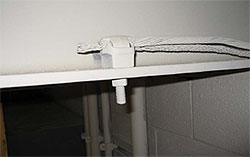 Figure 5. A building steel grounding conductor and a braided lightning rod (air terminal) down-conductor are shown connected to a painted steel member by an unapproved bar-tap. Building steel connection to earth was unknown and the connection has high resistance. The air terminals should have been earthed to the grounding electrode system or ring ground outside the building.
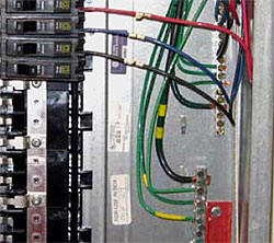 Figure 6. A panel serving communications, phone and network equipment contains two grounding bars (at right). The lower one contains both isolated ground wires (IG, yellow-green) and electrical equipment ground (green) conductors. This non-compliant condition negates the IG, which was also incorrectly bonded to the UPS by-pass switch downstream.
 - Additional discrepancies included excessively long grounding conductor runs to surge protection devices in the telephone system. Those runs shouldn’t exceed three feet, yet some were 70 ft long. In order for surge protection devices to function properly — if at all — they must be connected to a robust grounding system, using leads as short as practical. An incoming surge will otherwise find an alternative, lower-impedance path, possibly through sensitive equipment.
Serious Problems with Tower/Transmitter Grounding
The sloppy installations described above probably decreased the facility’s overall power quality, but most of them likely didn’t contribute to lightning damage. That damage was caused in large part by the more serious mistakes Cookson found at the tower/transmitter. There, he discovered three separate connections to earth: one from a single tower leg (and it was poorly made at that, with ground resistance of 60 ohms) (Figure 7); another one, at 35.4 ohms, from the outdoor grounding bus (Figure 8) and a third one measuring 42.5 ohms from a sub-panel feeding the transmitter building (Figure 9). Conductors from the latter two sources were joined, thereby setting up a ground loop.
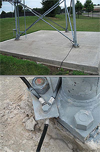 Figure 7. One of three existing earth connections at the antenna tower was made to a tower leg (upper photo). It terminated at an 8-ft grounding electrode. The mechanical connection to the tower (lower photo), was made to a galvanized and painted steel tab, which was itself bolted to the galvanized steel tower support flange. This connection method imparts high resistance and is not recommended.
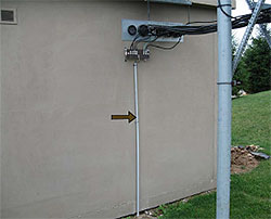 Figure 8. A separate earth connection at the tower/transmitter site was made from the outdoor grounding bar seen just beneath the wall penetration. The grounding conductor (in conduit, arrow) connects with the tower ground at the opposite side of the building, forming a three-way ground loop.
There was no neutral-ground bond in the panel, so a separate grounding conductor had been routed back to the safety center’s grounding system. A lightning strike to the tower would produce a huge ground potential rise (step potential) across the entire tower/transmitter footprint, creating loop currents among the two existing electrodes and three ground connections. Those currents were easily strong enough to travel down that separate grounding conductor and damage equipment elsewhere on the facility’s grounding system.
 Figure 9. The new grounding/earthing system at the communications site includes three new driven electrodes at the tower, an AWG 4/0 bare copper ring ground surrounding the tower and bonds to the existing system. A ground loop between two existing electrodes was eliminated, as was a separate ground conductor leading from the building to the safety center.
The Fix
An electrical contractor was called in to correct discrepancies in the safety center’s electrical grounding system. Cookson verified that those corrections had been made and then personally addressed the situation at the tower/transmitter. An overview can be seen in Figure 9.
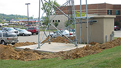 Figure 10. A new 3-ft deep trench surrounding the tower and remote communications building contains an AWG 4/0 bare copper ring ground, three new electrodes and connections to the tower, two existing electrodes and the building’s electrical system ground.
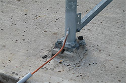 Figure 11. An exothermic weld bonds a grounding conductor to a tower leg. Zinc galvanize was removed from the leg prior to making the weld. Protective paint covers the new joint area.
He began by installing an AWG 4/0 bare copper ring ground in a 3-ft deep trench around the tower (Figure 10). He drove three 10-ft copper-clad ground rods and then bonded each tower leg to an electrode, and the electrodes to the ring, using exothermic welds (Figures 11 and 12). He completed the earthing system by bonding new copper grounding conductors from the ring to the outdoor grounding bar (Figure 13) and tied the entire system to the existing ground at the small unmarked outdoor panel and to the indoor ground bar (Figure 14). He also installed a new ground bar as a collector for telephone system surge protection devices, thereby shortening the ground path for those devices. All connections are either exothermic welds or UL 467- approved compression terminals.
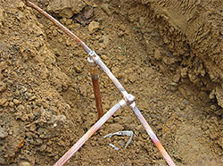 Figure 12. Exothermic welds connect new electrodes with the copper ring ground. A conductor from one of the tower legs is seen at lower left.
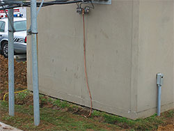 Figure 13. A new AWG 4/0 copper ground connector bonds the outdoor ground bar to the ring using an exothermic weld and an approved UL 467 compression terminal.
Cookson also removed the separate grounding conductor that had been run from the outdoor panel at the remote communications building to the safety center’s electrical system. In so doing, he eliminated the possibility that a future lightning strike to the tower — which was inevitable — could feed energy to equipment in the safety center.
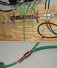 Figure 14. An indoor grounding bar (upper photo) connects cable-shield ground conductors from the outdoor bar plus telephone and communications-equipment grounds in the building. An approved UL compression fitting (lower photo) now connects the bar to the new earthing system.
Did it work? Experience to date indicates that it does. The tower has been struck numerous times since Cookson completed his upgrade in 2008, yet there has not been another incidence of equipment damage, either at the tower or in the safety center. The emergency generator has energized several times, indicating interruptions in utility power, but the grounding system works as intended, and Chief Heck says he feels “a lot more comfortable”.
The Principals
 Richard Heck, now retired, was Chief of the Jackson Township Fire Department at the time this article was written. The department provides service to more than 43,000 residents.
 Carles D. Moore was Central Maintenance Director for Jackson Township at the time this article was written.
 Tim Cookson, CPQ, PAI, is a senior electrical engineer with PowerEdge Technologies, Inc. a Canton, Ohio-based firm specializing in power quality issues, including power quality and power management surveys, harmonic assessments, grounding and electrical system testing, operating environment assessments and site planning services for sensitive electronic equipment. The company also provides educational services to industrial, trade and educational organizations. For further information, call (330) 494-7314, Fax (330) 494-7750.