![]() Download PDF Version [4.8Mb]
Download PDF Version [4.8Mb]
- Involta-Marion
- A Copper Producer Understands Reliability
- Involta-Akron
- Robust Copper Grounding System
- Copper-Only for Reliability
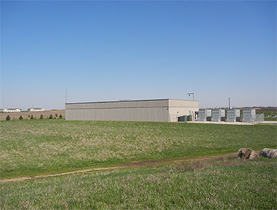
Involta's Marion, Iowa data center is one of seven that the company owns and operates in the Midwest. Like other Involta centers, it is served by redundant utility feeds. Visible to right of the center are its two utility transformers and four back-up generators. Indoors, those power sources feed independent A and B distribution circuits that extend redundantly to every server rack and all mission-critical equipment. Copper conductors are used exclusively for all power and grounding circuits, including the buried 500-MCM bare copper ground ring that surrounds the building.
Colocation data centers, or colos, provide secure IT space to clients who opt to outsource some or all of their IT and communications operations. Clients enjoy reduced costs thanks to shared infrastructure and overhead expenses and gain increased uptime due to the redundancy and sophisticated monitoring features that most high-quality operators provide. Top-level colo operators may also offer a variety of IT-related services ranging from basic consulting to data center design and construction.
Cedar Rapids-based Involta™ is one such company. It operates data centers in Cedar Rapids and nearby Marion, Iowa, plus two in Duluth and one each in Boise, Akron, Ohio and Tucson. All were designed in-house and constructed under company supervision. The centers’ locations and features are intended to serve secondary data-center markets in areas previously underserved by the industry. All offer their tenants 100% guaranteed availability. Designs differ somewhat among the seven centers owing to location and changes in codes and standards over time. This article describes Involta’s Marion and Akron centers. Both offer Tier III1 - scale redundancy in power and cooling, and like most other Involta sites, both are LEED-Silver rated to reduce users’ energy costs.
Involta-Marion
Jeff Thorsteinson is Involta’s Chief of Security. He has witnessed the company’s centers evolve and has contributed to the design of several. Involta-Marion is one of the company’s earlier colos, but the 300-rack, 18,000-sq ft center has all of the features you’d expect in a Tier III facility. “Marion is an excellent location for a data center,” said Mr. Thorsteinson in a recent interview. “We’re safe from flooding, being near the highest point in the county, and we have a direct tie to the Linn County Rural Electric Cooperative’s Main Headquarters Substation, which is located right across the alley from our center.” (Figure 1) “Our independent second feed comes from the utility’s County Home Road Substation about five miles away. One of our two 2,500-kVA utility transformers is fed by the 38-kV Main Headquarters substation; the other by the 12.4-kV County Road feed. Each transformer has sufficient capacity to supply 480-V power to the entire facility (Figure 2).
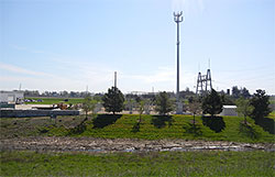 Figure 1. One of Involta-Marion’s two utility feeds is literally next door. The second primary feed originates at another substation about five miles away. Redundant utility feeds are a primary requirement for Tier III compliance.
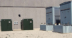 Figure 2. Involta-Marion’s two independently fed 2500-kVA utility transformers are seen at left. Two of the center’s four 750-kVA diesel generators are visible at right. Either of the transformers and any three of the generators can fully power the data center. Additional generators can be added as the data center expands. Not visible in the photo is a buried web of 4/0 AWG copper grounding conductors that connect all equipment and the switchyard’s fence into the center’s single-point grounding system.
“Our prime back-up loaders are our four Caterpillar 750-kVA diesel generators (Figure 2), any three of which can supply the entire center. They’re capable of starting and supplying load in less than a minute. Each unit is started and tested once a week and load-tested every month. All of that activity is automated through our programmable logic controller. That’s important because redundant power delivery to data centers is the number one differentiator with respect to tier levels according to the Uptime Institute — and to our customers! Involta’s data centers all have redundant power supplies.”
Separate feeds from the pair of 2,500-kVA transformers connect to a switchboard that integrates the transformers and the generator feeds in the event of an interruption in service. Power then enters the center as two “A” and “B” buses rated at 2000-A each, and then to isolated UPSs rated at 900-kVA apiece. Both circuits are equipped with surge protection devices; harmonics are filtered out by strategically placed isolation transformers. Step-down distribution transformers power the A and B branch circuits that feed the servers and other equipment. Besides providing protection from outages, the independent A and B circuits enable equipment to be taken out of service for maintenance while the rest of the center remains fully operational.
Involta chose to cool its Marion center from overhead ductwork. Power circuits are fed to server racks by way of conduits buried beneath the center’s concrete floor. Distribution panels direct the power leads to overhead trays and from there to server cabinets, Figure 3, which shows connections to the A and B circuits.
Involta-Marion’s customers may opt to ground their server racks redundantly, i.e., from the cabinets and racks and the equipment grounding conductors. Such redundant grounds are transmitted overhead as 3/0 AWG cables to wall-mounted grounding bars found in all IT rooms, Figure 4. Heavy-gage 500-MCM copper grounding conductors connect the bars to the facility’s main grounding bar, and from there to the exterior grounding system.
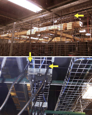 Figure 3. Several types of overhead trays are used to direct power cables to server racks. The paired conductors shown in the photos (arrows) house the A and B circuit conductors for individual servers.
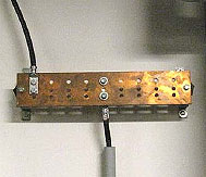 Figure 4. Shown in the figure is one of several wall-mounted grounding bars that connect conductors from overhead trays (upper-left 3/0 AWG cable) to an 3/0 AWG collector cable (at bottom) leading to the facility’s main grounding bar. Larger 500 MCM cable connects the MGB to exterior grounding system.
The exterior grounding system itself includes a buried, bare-copper 4/0 AWG ring-ground running along building’s periphery and a series of 10-ft-long driven copper-clad electrodes that are bonded to the ring at appropriate intervals. Copper down-conductors from the rooftop lightning protection system are also bonded to the ring. The system, including interior and exterior sections, therefore constitutes a single-potential reference point to earth.
The entire grounding system, including its ground resistance, is re-evaluated every two and a half years as part of normal preventive maintenance. The interval may differ at other centers depending on local soil conditions and other factors. In each case, however, the ground resistance is maintained below five ohms.
Mr. Thorsteinson summarizes Involta‘s reliance on copper in no uncertain terms by emphasizing that “Involta uses 100% copper distribution at all of its data centers. The substation connections may be aluminum in some instances depending on the the utility supply, but we only use copper from the switchgear on down. Of course, all grounding-system conductors are also exclusively copper. Because Involta offers its customers 100% availability, we can’t afford not to use the best materials with the best and most reliable connections.”
A Copper Producer Understands Reliability
PMX Industries is a leading copper and copper-alloy producer. Among other accomplishments, the company has developed a line of antimicrobial copper alloys, in a variety of colors, which hold considerable promise to reduce touch-transmitted infections in hospitals and other public facilities. The company’s headquarters, main U.S. plant and R&D operations are located in Cedar Rapids.
Rouja Daskalova is PMX Industries’ Manager - Application Development and, among other duties, oversees the company’s IT operations. As such, she is well aware of the fact that data centers can be and often are located great distances from their customers in order to access certain features. But Ms. Daskalova and PMX management preferred to keep their sensitive research data close to home, provided that the chosen site offered high levels of security and reliability. After a thorough evaluation, they selected Involta-Marion as their off-site data repository. As Ms. Daskalova recalls, “We liked the fact that they have dual power supplies and multiple generators in case there was an outage. We have tornadoes and we have a nuclear power plant nearby, and Involta has prepared for all those contingencies. They have a very impressive reliability plan. I am also aware of their dual branch circuits. We are concerned about where our data resides because we have a lot of know-how in that data, and we wanted to make sure that it’s in a very secure place. We’re also happy that they’re local because that allows us quick access to their facility, and we can address any concerns on the spot if we need any help.
“It is ironic that PMX is in the copper industry and Involta has invested so much in copper wiring, and copper tube for their redundant power supplies and air conditioning. We are very proud to be a supplier of this material and we’re glad to see that our own product is helping to keep our data safe.”
Copper = reliability: who would know that better than a copper producer?
Involta-Akron
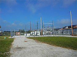 Figure 5. With only one utility serving its Akron location, Involta elected to build its own substation adjacent to its data center. Redundancy is achieved by having duplicate breakers, transformers and switchgear for A and B circuits.
One of Involta’s newest data centers is located in Akron, Ohio, approximately 40 miles south of Cleveland. It is 26,400 square feet in size and houses 300 servers in two side-by-side server halls. Like Involta’s other colos, it was built for the secondary market, with customers ranging from small enterprises that need only one rack to municipalities and large medical facilities.
Tom Lang is the center’s manager. He explained that, in addition to the Akron-Canton area itself, the center’s location offers access to Pittsburgh, Cleveland, Columbus and Toledo, all accessible by a two-hour-or-less drive. The 60-mile distance of each is important here because it represents the current limit for real-time synchronous data replication needed for redundancy and backup.
Ohio Edison is the only utility serving the Akron center’s location, so Involta opted to build a wholly-owned substation on its property, Figure 5. The substation is fed by a 1.3-mile, single-line, 13.8-kV utility feed that serves two independent breakers, dual transformers and dual switchgear. The two sets of equipment in the yard establish the redundant power feeds that constitute the downstream A and B circuits. Switchgear in the substation yard can transfer feed from one transformer to the other in the event of a loss of power on either side. All transformers in the yard, and for that matter in the data center itself, are 100% copper-wound for reliability and high efficiency. The substation yard is underlain by a buried, three-foot-by-three-foot, 500-MCM copper grounding grid that extends three feet beyond the fence. All equipment in the yard, as well as the fence and gate, are bonded to the grid, Figure 6. A buried 500-MCM grounding conductor connects the grid to the ring-ground and grounding electrode array that surrounds the nearby data-center structure, Figure 13. The ring-ground, and arguably the entire contiguous mass of buried copper, therefore serves as the low-resistance, low-impedance, single reference point for the facility’s ground.
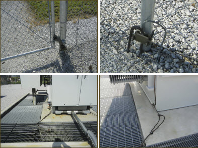 Figure 6. All equipment in the substation yard is grounded to a buried 500-MCM bare copper grid that extends three feet beyond the fence, which, along with the gate, is also bonded to the grid. A copper grounding conductor is run through a buried conduit to the ring-ground surrounding the perimeter of the nearby data center. All above-ground connections are mechanically bonded with approved connectors.
Installed in parallel with the utility feeds are two 1-MW back-up generators, Figure 7. As Mr. Lang explained, “The generators are paralleled, allowing us to bypass across the units. A programmable logic controller (PLC) monitors, or as we say, facilitates utility and emergency power. A switch is in place to transfer power, if needed. In fact, all power elements have their own automatic transfer switches, so if we have an issue on one side, that transfer switch will take over and let us continue to operate without interruption."
Sets of 1600-A power cables from the substation yard and the generators connect to switches, from which power is fed to the center’s two electrical rooms. The rooms are dedicated to the A and B circuits, respectively. There, voltage is stepped down to 480/277 V for distribution to mechanical devices situated around the data center and to the mechanical spines in the two data halls. Voltage is stepped down again, to 208 V, in the data halls. It is then fed through two UPSs for protection/filtering and from there to distribution on the floors via Starline® busways containing A and B circuit conductors for each cabinet, Figure 8.
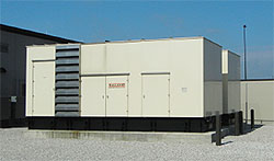 Figure 7. Two 1-MW generators provide emergency power to the data center in the event of a utility outage. The units can be operated separately or in parallel, as needed. A PLC controls the generators, utility power, UPS units and a battery farm.
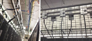 Figure 8. Power is fed to racks via overhead Starline busways (left). Both A and B circuits run in the busways, but the photo at right shows their separate feeds to the racks.
Robust Copper Grounding System
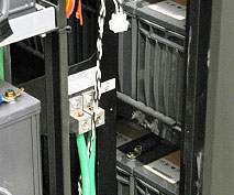 Figure 9. Dual grounding conductors are shown bonded to a rack in one of the center’s battery farms. The green wires are routed upward to a cable tray, and from there to a ground bar mounted on a nearby wall.
The grounding system at Involta-Marion can best be described as thorough and robust. The large-gage copper grounding conductors for outdoor electrical components are matched, where needed, by their counterparts inside the data center. Low-risk elements such as the racks in the center’s battery rooms, for example, may be grounded with #6 AWG, Figure 9, that is run in overhead trays to wall-mounted grounding bars and from there to the main grounding bus (MGB). The larger 3/0 AWG grounding conductors from server racks, Figure 10, follow a similar path but terminate at separate grounding busbars such as the one shown in Figure 11.
However, Mr. Lang points out that “Customers typically install their own equipment in rack space provided by us, and it is their choice to take grounding to that level. Involta’s responsibility is to ground to the rack and it is up to the customer to decide whether to ground their equipment to the rack or not.”
Grounding cables from both data halls, as well as grounding cables from mechanical equipment and elements such as the battery farm mentioned earlier, are bonded at the facility’s MGB located elsewhere in the building, Figure 12. Single 500-MCM grounding conductors lead from the two data rooms’ SGB grounding bars to the MGB, which also collects grounding conductors from the substation, generator and transformer yards plus the rooftop lightning protection system. Finally, a collection of #4 AWG and 4/0 AWG are fed in underground conduit to the facility’s water system, a driven copper-clad electrode and the common earth connection at the buried copper ring, Figures 13.
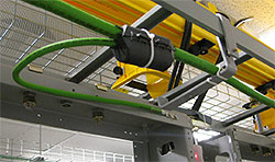 Figure 10. An 3/0 AWG overhead grounding conductor (foreground) collects grounding current from racks, which in turn are bonded to servers if the customer chooses to do so.
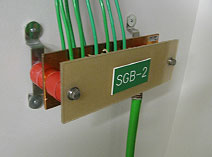 Figure 11. Grounding conductors from racks and mechanical equipment associated with one data hall and collected at a wall-mounted copper busbar. A similar arrangement exists at the second data hall. The large cable leading downward is routed in conduit under the floor to the main grounding bar located elsewhere in the center.
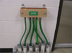 Figure 12.Grounding conductors from throughout the center meet at the main grounding bus (MGB). From here a single large conductor is run in conduit under the structure to the buried ring-ground that surrounds the center.
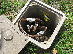 Figure 13. A 500-MCM bare copper ring-ground runs along the periphery of the data center structure. Grounding conductors from the MGB, the rooftop lightning protection system, the substation yard and the transformer yard are bonded to the ring, which serves as the single common reference grounding point for the entire data center.
Copper-Only for Reliability
Involta, and Mr. Lang in particular, are not apt to use or recommend aluminum for cabling in the facility. Mr. Lang explains: “I had an experience in a facility I formerly worked for. Lugs consistently came loose on aluminum feeders, causing outages we couldn’t afford. Plus, there was the cost of bringing in electricians. We finally brought in some engineering help, and on their recommendation we replaced the aluminum with copper to avoid issues going into the future. Copper, although it cost a bit more off the shelf than aluminum, provided overall cost savings through fewer interruptions and fewer electricians’ visits. With copper, we bought reliability! I learned from that experience that copper itself is reliable, and that it is not only important for our customers, but that it gives us peace of mind at the end of the day.
“We talk with a lot of people about the facility side of data centers, and the one component they forget about is grounding. I don’t know why, maybe it’s just forgotten, but grounding is definitely the critical item in the reliability of data centers, and copper is one the most important, if not the most important component to ensure that reliability.”
Well put, Mr. Lang, we couldn’t have said it better ourselves.
The Principals
 Jeff Thorsteinson is chief of security for Involta. He can be reached at PO Box 1986, Cedar Ra, IA 52406, Mobile 319.551.5168, [email protected].
 Thomas Lang is the data center manager at Involta’s Akron facility. He can be reached at PO Box 2133, Akron, OH 44309, Office 330.752.7164, Mobile 216.978.2226, Fax 330.374.4062, [email protected].
 Rouja Daskalova is Manager - Application Development for PMX Industries, Inc. She can be reached at 5300 Willow Creek Drive, Cedar Rapids, IA 52404.
 Involta™ is a world-class data center operator, with currently (2013) seven locations. Each serves a variety of tenants, primarily in secondary markets. The centers were built at different times in slightly different electrical architectures, but reliability is the facilities’ first and common requirement. The company therefore utilizes copper for all power and grounding cables downstream from the switchgear. There are design lessons for every critical application in this case study.
 PMX® Industries, headquartered in Cedar Rapids, Iowa, produces a wide range of copper materials in strip, coil, sheet, plate and tube including high-precision alloys for electronics, EcoCopper™ green building materials, and MicroGuard™ antimicrobial copper alloys.
Footnotes
 The Tier system based on criteria originated by, and still administered by the Uptime Institute. The system ranks reliability in Tiers numbered I through IV, the latter being the highest. The Tier level attained by a data center is based, in general terms, on redundancy of mission-critical systems. Tiers can be “officially” certified by the Uptime Institute, but are frequently claimed by facilities and certified by independent audits. See the Uptime Web site for a complete explanation.