![]() WATCH VIDEO: Orange County 911: Lives Depend on Power Quality
WATCH VIDEO: Orange County 911: Lives Depend on Power Quality
![]() WATCH VIDEOS: Apopka: Lightning Damage Alleviated by Retrofit - Part 1 | Part 2 | Part 3
WATCH VIDEOS: Apopka: Lightning Damage Alleviated by Retrofit - Part 1 | Part 2 | Part 3
- Systems Approach Needed
- It's much worse than that!
- Apopka Site
- Clarcona Site
- Reedy Creek Site
- Costs vs. Benefits
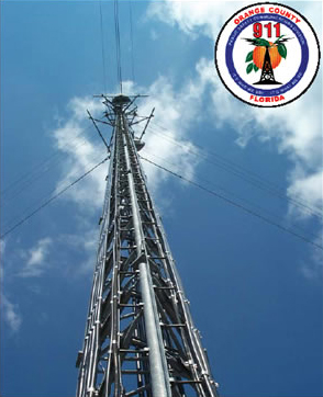 Orange County, Florida's emergency response system is based at Apopka, an Orlando suburb. Dispatchers at the facility take citizens' 911 calls, then contact appropriate agencies by way of a 28- channel radio network. The 280-ft (85-m) antenna tower, one of 11 in the system, is a frequent target for the area's many lightning storms. High-resistance grounding enabled a lightning strike to destroy expensive transmitter equipment here. Similar incidents have cost taxpayers more than $2 million over 10 years, but damage ceased when the county installed a low-resistance, all-copper grounding system.
The county defends its 820,000 residents 150,000 of whom are seniors with an extensive emergency response system. When a citizen calls 911, dispatchers notify response teams by way of a 28-channel radio network that includes eleven transmitter sites, all equipped with tall antennas to cover the county's more than 900 square miles. But what happens when lightning disables the communications system?
Tom Sorley knows. Sorley is supervisor of Radio Services of Orange County's Public Safety Communications Division, located in Orlando. It's his job to keep the communications lines open, and the job hasn't been easy. "We're in the most lightning-prone area of the country," he says, adding, "our antennas are up on 280-ft (85m) lightning rods!
"One or two strikes per month on a large tower like the one at our Apopka base site are routine between May and October. They don't all do damage, but we have lost our entire network at times, and every public service agency is in jeopardy when that happens. We operate more than 15,000 active IDs (each radio-equipped emergency vehicle constitutes one ID, for example). Imagine what would happen if we absolutely had to dispatch a police cruiser and couldn't reach it!
"Lightning has also cost us a lot of money. The Apopka site took a $13,000 hit to some transmitters the other day, and we lost another $25,000 at Clarcona earlier this summer. System-wide, we've been running between $100,000 and $200,000 per year in lost equipment due to lightning strikes. That's almost two million dollars over the past 10 years!"
Back to TopSystems Approach Needed
Lightning protection is essentially the process of directing strikes to ground and away from where they can cause damage or injury. Doing that right requires a properly designed, low-resistance grounding system. But since many buildings especially emergency service facilities have grounding systems that meet electrical codes, why did Orange County have a problem?
Sorley explains: "Our facilities complied with the codes that were in effect when they were built. Lightning protection has come a long way since then, but codes and protection systems take awhile to catch up. Also, our system was designed and built by a number of different contractors over the years. No single individual or contractor understood, nor was responsible for, grounding as a total system. Grounding and its maintenance were just something everyone took for granted. What we really needed, and what we now have, is a total systems approach to lightning protection."
Back to TopIt's much worse than that!
Orange County is active in a domestic terrorism task force in Florida, created by Governor Bush. While chairing its communications committee, Sorley was led to John West, founder of Power & Systems Innovations (PSI), a 12-year-old Orlando-based company specializing in power quality, grounding and lightning protection. West understood what Sorley was up against, having upgraded the 911 headquarters grounding system in nearby Winter Park.
"I invited John to inspect a few of our sites," Sorley recalls, "after which I asked him if he thought our systems were in bad shape. 'Oh no,' he answered. 'It's much worse than that!' That got my attention, so we developed an action plan and got to work."
Sorley engaged Donnelly Engineering, based in Orlando, design the new grounding systems. West served as a technical consultant. Sorley split the project into two parts. "In Phase I," he recalls, "the issue was to protect lives by making certain that another lightning strike wouldn't take us off the air. In Phase II, we'll go back and add improvements like better surge protection and tie-ins to other systems that aren't directly part of the 911 emergency response network."
THREE SITES PROVIDE EXAMPLES
Improvements at three of the county's transmitter sites illustrate work accomplished system-wide under Phase I. The sites are in Apopka, Clarcona and Reedy Creek in the Orlando suburbs.
Back to TopApopka Site
The Apopka site houses the 911 communications hub, along with county offices, courtrooms and dispatchers. A 280 foot (85 m) antenna tower, complete with grounding and lightning protection systems, was installed 10 years ago. Located immediately adjacent to the building, the tower is surrounded by paved area on the remaining three sides.
West found that the grounding "electrode" serving the tower and transmitter room was actually a length of ordinary steel all-thread rod driven into the ground near the tower base. Resistance to earth was an astonishing 550 ohms (Figure 1), 22 times the maximum resistance cited by the National Electrical Code and more than two orders of magnitude higher than the level recommended by such standardssetting organizations as IEEE and TIA/EIA. The makeshift electrode was supplemented by a length of buried cable (counterpoise) which, in turn, was connected to one of four copper strips leading to copper firewalls. West discovered that the contractor had simply buried three of the copper strips in the ground, never connecting them to the electrodes.
Donnelly and West installed a new 60-ft (18-m) copperclad electrode close to the tower (Figure 2) on the premise that a lightning strike would tend to travel vertically. A deep electrode was used because of the soil's high resistivity. The new electrode's resistance is an acceptable 4.3 ohms.
 Figure 1. The Apopka antenna tower was originally grounded to a length of steel all-thread rod and a counterpoise (a length of buried bare AWG 4/0 copper cable). Ground resistance was 550 ohms, far too high to provide useful grounding and excessive even for lightning protection. Lightning surges had often bypassed the electrode, destroying equipment inside the transmitter building.
 Figure 2. Bare AWG 4/0 copper conductors are exothermically bonded to a new 60-ft (18-m) grounding electrode at the Apopka tower base (lower left) replacing the all-thread rod. Resistance to earth is 4.3 ohms.
Donnelly and West next ran AWG 4/0 leads from the new electrode to a copper bus on the tower (Figure 3a), which was then connected to a second bus (Figure 3b) which served as a junction point for the coaxial cable shields, and to the firewalls and copper strips shown in Figure 4. The copper strips were left in place but were supplemented with additional lengths of AWG 4/0, and all four strips were bonded to the counterpoise.
 Figure 3. Weatherproofed leads from antenna cable shields (Figure 3a) are bonded to the large bar (Figure 3b); and a lead from there connects to a second copper bar (Figure 3a, lower right), which was added for ease of access. An exothermic bond connects the bar to the grounding electrode.
New, AWG 2/0 grounding conductors were piggybacked over existing AWG 2 conductors at the tower's three sets of guy wires (Figure 5). The heavier conductors were run to three new 60-ft (18-m) grounding electrodes. Chemical-type electrodes had been installed 10 years earlier, but because they had never been serviced, resistances had risen to between 35 and 64 ohms.1
 Figure 4. Only one of the four copper strips shown leading from the site's two antenna cable firewalls was actually connected to the counterpoise. The other three were simply buried. The copper strips are now augmented with AWG 4/0 copper securely bonded to the firewalls and to the new grounding electrode.
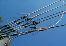 Figure 5. One of three sets of five guy wires, each supporting the Apopka tower. New AWG 2/0 ground leads from the wires connect to a new lowresistance electrode. Resistance at the new electrodes ranges from 5.3 to 6.7 ohms.
Resistance of the new deep electrodes ranges between 5.3 and 6.7 ohms. A clear indication of their effectiveness can be seen in the 150-160 mA of RF current they draw off the guy wires.
Leaking Roof + Poor Grounding = Lost Equipment
The equipment room houses more than $2 million worth of transmitters, switches and auxiliary equipment (Figure 6). West found the two rows of equipment racks bonded to the firewalls by way of a halo ground, and from there, to the main grounding electrode and counterpoise outdoors (Figure 7a and 7b).
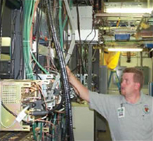 Figure 6. Orange County technician Dave Hazen checks transmitter equipment at the Apopka site. The room, one of eight like it in the county system, contains more than $2 million worth of communications gear. Equipment racks were originally grounded by way of a halo ground circling the walls, but equipment chassis themselves were never bonded to the racks.
 Figure 7. Schematic diagram of the Apopka site grounding system: as originally installed (Figure 7a), and as upgraded (Figure 7b). Green lines identify grounding conductors; copper color indicates new grounding plates. Improvements include bonding to equipment cabinets and racks, an additional halo ground, copper grounding plates, a lowresistance grounding electrode and exothermically welded bonds.
The equipment chassis (cabinets) themselves hadn't been bonded to the racks. During a thunderstorm in mid- 2002, a leak in the building's roof left a trail of water down one of the racks and onto the concrete floor. A lightning strike followed the moisture trail (wet concrete is a pretty good conductor), destroying expensive transmitters and leaving the 911 system short by two communications channels (Figure 8a and 8b).
 Figure 8a. Water stains on an equipment cabinet left by a leaking roof. The moisture trail, which continued to the concrete floor, allowed a lightning strike to destroy expensive transmitters and took two communications channels off the air.
 Figure 8b. Dave Hazen holds circuit boards destroyed by the lightning strike. The damaged equipment put public safety at risk and cost $13,000 to replace. Lightning caused almost $2 million in similar damage to the entire system over 11 years. An all-copper grounding system installed in 2002 put an end to the damage, improving public safety and eliminating high repair costs.
The new grounding system designed by Donnelly includes several features intended to prevent that sort of incident from recurring:
- First, all equipment chassis were firmly grounded with AWG 2 copper. The heavy leads are bonded to a series of copper ground plates mounted at the top of the overhead rack supports. The plates are connected to each other in a halo ring made from bare AWG 2/0. Equipment racks are also bonded to the plates (Figure 9a).
- A second AWG 2/0 halo was mounted on the comm room walls and connected to the inner ring, again using copper plates. Bolted connections on the plates ensure sound bonding. More AWG 2/0 connects both halos to the copper firewalls.
- Rubber mats were placed under equipment racks to help preclude a conductive path (Figure 9b).
- Finally, an exothermically bonded connection was made between the halos and a conductor leading directly to the new grounding electrode system.
 Figure 9a. A copper plate connects several equipment chassis grounding conductors with an AWG 2/0 halo ground (upper left).
 Figure 9b. Insulated mats installed under equipment racks at Apopka help prevent lightning from seeking out a watersoaked concrete floor, as it did after the site experienced leaking roof.
The communications system at the Apopka site is powered by the building's electrical system; however, the only grounding circuits between the two systems are the green wires in branch circuits. This arrangement is Code-compliant but not recommended, and Donnelly and West will improve it in Phase II, when both grounding systems will be interconnected. This change will create a robust and reliable ground path for the entire Apopka complex.
Back to TopClarcona Site
The Clarcona transmitter site (Figure 10) is smaller than the Apopka hub, but Donnelly and West found it to be plagued with similar problems. Like Apopka, the site had taken severe lightning damage due to high resistance electrodes, a lack of proper bonding (Figure 11), and inappropriate grounding at equipment cabinets.
 Figure 10. Like the Apopka hub, Orange County's smaller Clarcona site suffered from high ground resistance, inadequately maintained chemical electrodes, poor bonding and ungrounded equipment cabinets. Upgrades include a new 60-ft (18-m) deep electrode with less than 5 ohms resistance, firm bonding of all connections, installation of heavy copper grounding conductors to all equipment cabinets plus new halo grounds in the comm room.
 Figure 11. Corrosion raised resistanceat an existing cable shield ground connection on the Clarcona tower.
The total value of equipment at the site is nearly $2 million, not counting $800,000 in equipment belonging to the local community. The $25,000 loss the site suffered in 2002 seems small but, as Sorley observes, "Communications is a rapidly changing technology, and some of the older equipment we lose has to be upgraded with newer models. Its not just the equipment that is destroyed, but also every unit like it at all of our 11 sites has to be changed in order to maintain compatibility. That multiplies the cost of a single strike."
The grounding team's first order of business was to replace high-resistance grounding electrodes at the tower and guy wires with five 60-ft (18-m) copper-clad rods. The new electrodes register only 3.4 ohms resistance.
AWG 2/0 conductors were bonded to the tower and to the station's two firewalls. An obviously corroded grounding connection to the tower was replaced with a 1/4-in (6.3-mm) thick copper plate (Figure 12).
 Figure 12. A copper bar, large conductors and exothermic welds form secure bonds to the Clarcona tower, replacing the flimsy connection shown in Figure 11.
Clearly marked grounding terminals on equipment cabinets were never connected (Figure 13). As at Apopka, the oversight left the cabinets grounded only through cable shields and the green wires in their respective power cords. The installation was not in accordance with the manufacturers instructions, and not adequate from the standpoint of lightning protection.
 Figure 13. A clearly marked but unused grounding terminal, evidence that equipment cabinets had not been properly grounded. Cabinet racks were grounded, but chassis were grounded only through cable shields and power cords. The practice did not provide adequate lightning protection.
Donnelly and West bonded the cabinets and racks with AWG 2 copper strung overhead to connect with copper plates on a new AWG 2/0 halo ground on the walls. The halo, which also functions as a grounding point for air conditioners and other auxiliary equipment, is bonded to the copper firewalls and to the main grounding electrode system outside the building (Figure 14).
 Figure 14. Copper plates in a halo ground surrounding the Clarcona site communications room. The plates are bonding points for ground leads from equipment racks and cabinets and auxiliary equipment such as air conditioning units.
Reedy Creek Site
 Figure 15. Reedy Creek, one of Orange County's two remote repeater sites, is underlain by highresistivity "sugar sand." Poor soil conditions, along with neglected chemical-type electrodes, raised the site's ground resistance to more than 1,000 ohms.
Chemical-type electrodes had originally been installed to enhance the soil conditions. (Salt in the electrodes leaches into the ground, raising conductivity.) As at Apopka, the electrodes had not been maintained, and at the time West inspected them, resistance was more than 1,000 ohms.
The site was also equipped with an AWG #2 tinned copper ground ring at the base of the transmitter building. The ring was in satisfactory condition, so West and Donnelly tagged their new system to it (Figure 16a).
New electrodes had to be driven 120-ft (37-m) deep to gain satisfactory resistance
levels between 3.5 and 4.4- ohms in this case (Figure 16b). One electrode was installed at the tower base and four others outside the corners of the perimeter fence, about 15 ft (5 m) from the building. These were exothermically bonded to a new AWG 2/0 bare copper ground ring (Figure 17) at the fence and to lengths of AWG 2/0 extending to the pre-existing tinned-copper ring and its chemical electrodes. The resulting "star" grounding net directs lightning energy outward and into the ground far from the transmitter's sensitive electronic equipment.
 Figure 16a. Arrows identify new (foreground) and old (rear) grounding electrodes near the tower base (far right) at the Reedy Creek repeater, as seen during installation. Resistance of un-maintained chemical rods was higher more than 1,000 ohms. AWG 4/0 bare copper grounding electrode conductors are bonded with exothermic welds.
Figure 16b. Resistance of the new rods ranges between 3.5 and 4.4 ohms, levels that are both low enough to ground sensitive electronic equipment and suitable for reliable lightning protection.
 Figure 17. Schematic diagram of the Reedy Creek grounding system as originally installed (blue lines) and as upgraded (green lines). Upgrades include five new 120-ft (37-m) deep, low-resistance electrodes, an AWG 4/0 ground ring at the fence line, tie-ins to the existing system and exothermic welds throughout.
Costs vs. Benefits
The Phase I upgrade cost the county $150,000 in materials, labor and consulting fees. Public officials understandably think twice before spending that kind of money burying wire. But Tom Sorley is convinced that the county's investment will pay off. "We're talking about saving lives here, so our ultimate goal is to eliminate interruptions from lightning, period. We don't ever want any downtime! Since completing Phase I, we've gone through one-half of this year's storm season without problems. It may be too early to tell yet, but I think we have a winner.
"As for costs, you first have to look at what we're protecting. The entire emergency response system cost the taxpayers $30 million; the towers accounted for about a third of that. The major cost is tied up in very expensive equipment. Replacing and repairing that equipment has cost us nearly $2 million."
"Another benefit that's come out of this is a system-wide performance, inspection and maintenance program. It will enable us to monitor how we're doing, find areas that need special attention and provide records for future reference. The program also spells out specific preventive maintenance steps."
John West is confident that the new grounding system will do its job. "Bob Donnelly and I live and work here," he says. "And the public can see the result of our work with every storm. We've been at this business for a dozen years, and not one of our clients has ever lost a single piece of equipment after we installed a proper grounding system. We insist that our clients adhere to our specs and those specs always include copper. That's the only way we'll take a job."
That's confidence. That's copper.
Back to TopThe Principals
 John West is president of Power & System Innovations, Inc. (PSI), Orlando, Florida. Founded in 1992, PSI provides products, services and consulting related to power quality, power protection, surge protection, grounding, lightning protection and other anomalies that can damage equipment and/or cause data loss. PSI also designs, installs and services a broad range of protection equipment and systems. Further information about PSI can be found at the company's Web site, http://www.psihq.com, or by calling them at (407) 380- 9200 or (800) 260-2259.
 Robert L. Donnelly, P.E., is president of Donnelly Engineering, an Orlandobased electrical engineering and design firm specializing in grounding and lightning protection issues. He can be reached at (407) 351-3085, fax (407) 351-5149, email: [email protected].
 Tom Sorley is supervisor, Radio Services, of the Public Safety Communications Division, Orange County, FL, a position he has held since 2000. Mr. Sorley is responsible for all radio communications equipment in the county, including links to the 911 emergency response system. In 2002, Sorley initiated and supervised Phase I of the major upgrade to electrical grounding systems and lightning protection at the system's 11 transmitters. Mr. Sorley can be reached at (407) 836- 2792 and at [email protected].
Footnotes
 Chemical-type electrodes are quite capable of providing low resistances and are suitable for many applications with sensitive electronic equipment. However, the electrodes must be serviced according to manufacturers' specifications in order to guarantee that low resistance levels are maintained over time.