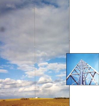
 The 1,200-ft KGBI-FM antenna tower and 100-kW transmitter in Springfield, Nebraska, is often struck by lightning. Until the station's owners installed a proper grounding system, lightning events caused expensive equipment damage and frequently took the station off the air. With its new grounding system in place, the station has developed such a reputation for reliability that it has been able to attract a tenant.
The station is located in the Midwest's notorious "tornado alley," and large thunderstorms occur regularly. KGBI's tall tower has received its share of lightning strikes, and every so often too often, in the eyes of the station's owners an exceptionally powerful strike would damage the transmitter or the all-important HVAC system, taking the station off the air.
Been There, Seen That
KGBI-FM's chief engineer, Bob Drake, had seen this sort of thing before at a sister station, KROA-FM in Donephin, Nebraska, and he had a strong hunch about the cause. "A few years ago we encountered serious lightning-related safety issues at KROA," said Drake. "We solved those problems by upgrading the station's grounding system. As soon as we did that, we noticed that the station's reliability and performance also improved dramatically. KGBI-FM is a listener-supported radio station. Not only are repairs expensive, but our commitment to 24/7 reliable radio required us to install a grounding system that would eliminate, or at the very least minimize, the possibility of lightning damage to our equipment. We believe we have now properly addressed this issue."
Drake called in grounding experts from Computer Power and Consulting (CPC) to recommend improvements to the grounding system at KGBI's unmanned transmitter-antenna site. CPC is an Omaha-based firm specializing in power quality and grounding-related problems. Earlier, the firm had successfully upgraded the grounding system at KROA-FM.
Martin Conroy, CPC's founder, describes what he found at the transmitter facility:
When the transmitter and tower were built, the site had a simple grounding system consisting of one chemical electrode, located between the transmitter building and the tower, plus two 10-ft (3-m) copper-clad rod electrodes between the tower and the perimeter fence (Figure 1). Additional rod electrodes were provided for each of the tower's nine guy wires. The backup motor-generator set, the HVAC units and the perimeter fence were not directly connected to the grounding electrode system. That was especially troubling, because if you lose either of those pieces of equipment, you lose the station. There was also a steel ice bridge between the tower and the transmitter protecting the antenna cable (Figure 2). The bridge provided a conductive path between the two structures but wasn't electrically bonded to either one.
 Figure 1. The grounding system originally installed at the KGBI transmitter-tower site, as found by CPC, contained a chemical rod serving as the primary grounding electrode, plus two supplemental electrodes connected to the tower. Air-conditioning units and a backup generator set were grounded through the electrical system. The perimeter fence was not connected to the grounding system.
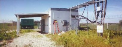 Figure 2. Overview of the KGBI-FM transmitter-tower facility. An ice bridge protecting the antenna cables can be seen at the upper right. The service entrance, center, is located directly above the primary grounding electrode. The motor-generator and its fuel tank are visible in the left background. HVAC units are behind the transmitter building.
Most of the grounding system was connected using bare AWG 2/0 copper conductors, large enough to meet NEC(National Electrical Code) requirements for this size installation. However, connections between the chemical rod and the service entrance ground bus and the tower and its electrodes were made via a perforated steel bar (Figure 3). That bar may or may not have been in compliance with the NEC, in which section 250 calls for main bonding jumpers to be of copper or other corrosion resistant material. In any event, the bar and its many dissimilar- metal connections were an invitation to corrosion.
The connection between the bus and the tower was made with a length of thin, 4-in-wide (100-mm-wide) copper strip. The strip was connected to a tower leg with ordinary hose clamps (Figure 4). I've seen copper strip used as a grounding conductor before; generally speaking, its high surface area presents low impedance to a high-frequency lightning surge. Maybe it does, but it sure didn't protect this station. The tower's two supplemental electrodes were connected using AWG 2/0 copper, and at least those conductors were welded to the tower's base.
 Figure 3. The original grounding system's chemical rod, bottom center, was connected to a perforated steel grounding bar, right, which also served as the facility's main grounding bus. Other connections to the bar include conductors leading into the transmitter building, grounding electrode conductors leading to two supplementary electrodes, and a 4- in (100-mm) wide copper strip, far right, leading to the antenna tower. Dissimilar-metal connections on the bar are vulnerable to corrosion.
 Figure 4. The base of KGBI-FM's tower sported numerous ground connections, some of which, like the copper strip leading to the chemical electrode, were of questionable quality, being secured to tower legs with ordinary hose clamps. Conductors welded to the foot of the tower lead to two grounding electrodes. Despite this assortment of grounding electrode conductors, lightning strikes to the tower occasionally passed into the transmitter building, damaging air-conditioning and transmitting equipment and taking the station off the air.
Inside the transmitter building, 8-in-wide (200-mm-wide) copper strip had been routed along the walls to form a partial halo ground (Figure 5). More strip was run under the transmitter equipment where it was connected to equipment cabinets.
 Figure 5. Inside the transmitter building, 8-in (200-mm) wide copper strip was fashioned into a partial halo ground running along the walls, from which connections(not shown) led to equipment cabinets. CPC added a full halo ground constructed from AWG 4/0 bare copper, although the strip was left in place.
We also found numerous ground-loop currents between the transmitter and the existing electrodes. Those currents possibly resulted from the variable quality of the electrical connections in the grounding electrode system. Ground loop currents at a broadcasting facility can lower the signal-to-noise ratio.
The station already had transient voltage surge suppression (TVSS) protection, but we wanted to improve the TVSS's grounding connection. Without a high-quality ground, a TVSS is useless. We also recommended that KGBI install a lightning protection system at the transmitter building and that their new grounding system should connect everything on the site, including the perimeter fence and outdoor auxiliary equipment.
Back to TopTotal System Upgrade
Here are CPC's specific recommendations, as installed by KGBI-FM:
- The chemical electrode was left in place as a supplement to the new electrode system. The two existing electrodes near the tower were also retained and tied into the new system. The primary electrode is now a 50-ft (15-m) deep, low-resistance copper-clad steel rod driven near the service entrance and the old chemical rod. Three additional deep electrodes were driven at points near the fence and adjacent to the emergency power generator (Figure 6). All electrodes were bonded together using bare AWG 4/0 copper.
 Figure 6.The improved grounding system at KGBI-FM. An existing chemical rod was retained. The new primary electrode is the nearest (to the transmitter building) of four 50-ft (15-m) deep, copper-clad steel rods installed around the site. The new system includes a ground ring outside the fence, a new halo ground and lightning protection. Copper plates mounted near the service entrance wall serve as the building penetration and main grounding bus, replacing the original steel grounding bar. All grounding electrode conductors are AWG 4/0 bare copper.
- An AWG 4/0 copper ring ground was installed in a 36-in-deep (914-mm-deep) trench outside the perimeter fence (Figure 7). Corrosion-resistant copper alloy clamps were used to bond the ring ground to the fence (Figure 8) and, via more 4/0 copper, to the antenna tower (Figure 9).
 Figure 7. A portion of the ground ring installed outside the transmitter site's perimeter fence. Bare AWG 4/0 copper conductors in the ring are bonded to the fence and to 4/0 conductors connecting all grounding electrodes, the antenna tower, auxiliary equipment and lightning protection system.
 Figure 8. The ring ground is bonded to the perimeter fence with listed, corrosion-resistant copper alloy clamps. Such clamps satisfy the NEC's requirement that the bond will ensure a permanent and effective grounding path.
 Figure 9. A listed bronze clamp, left, bonds the new grounding electrode system to the KGBI tower. CPC elected to use bronze clamps instead of exothermic welding, as had been done for the original grounding system, lower right. Both bonding methods are acceptable under the NEC.
- Additional AWG 4/0 copper connects the grounding electrode system to the emergency generator and its fuel tank and to the pedestal of the HVAC equipment. The HVAC equipment keeps the transmitter room at safe operating temperatures. Surge current from an earlier lightning strike to the antenna tower damaged the equipment and took the station off the air.
- A ring of AWG 4/0 copper was installed on the steel flashing of the transmitter building's impact-resistant (against falling ice) concrete roof. The ring connects new air terminals (Figure 10) and is jumpered to the steel-grid covered ice bridge (Figure 11). The jumper was needed because the bridge forms a conductive path between the building and the tower.
 Figure 10. CPC installed a ring of bare AWG 4/0 copper to connect air terminals mounted on the galvanized steel flashing surrounding the transmitter building's concrete roof. The building previously had no lightning protection.
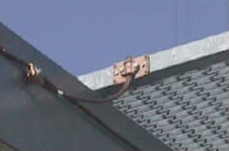 Figure 11. The air-terminal ring is jumpered to a steel ice bridge protecting the antenna wave-guide between the tower and transmitter building. The AWG 4/0 jumpers were recommended by CPC to ensure reliable electrical continuity between the building and tower.
- A new halo ground made from AWG 4/0 copper was constructed inside the transmitter building. Copper conductors descending from the halo were bonded to all conduits, cable trays and equipment cabinets in the building and to 1/4-in (6.3-mm) twin copper collector plates mounted on interior and exterior walls. Additional AWG 4/0 copper connects the plates to the ground bus in the service entrance panel and to the primary grounding electrode. The existing copper-strip partial halo was left in place and tied into the new system.
Cost of Protection Minimal
The entire system design, site preparation, materials and installation cost less than $10,000. As is usually the case, the heavy copper conductors made up only a small fraction of the total cost.
Was the exercise worth the effort? Absolutely! Since the new grounding system was installed in mid-2001, the antenna tower has seen an unusually severe series of thunderstorms. One powerful lightning strike actually burned through a ground strap on an antenna at the top of the tower. Even in that case, no damage was done to the transmitter or its auxiliary equipment.
Perhaps the longest-lasting benefit of the new grounding system is that the station now operates so reliably, the university has been able to attract a revenue-producing FM station as a tenant at the facility. It has also added a second transmitter building to the site. For KGBI-FM and its owners, $10,000 invested in a well designed and properly installed grounding system (and a few yards of copper) will continue to pay dividends for many years to come.
Back to TopThe Principals
 Bob Drake is chief engineer at KGBIFM (100.7 MHz), a noncommercial 100-kW facility owned and operated by Grace University, Omaha, Nebraska. Mr. Drake, a broadcast professional, understands how important proper grounding can be for reliable station performance. He can be reached at [email protected]. For information about Grace University, see their WebSite at www.graceuniversity.edu. KGBI's Web page can be found at www.thebridge.fm.
 Martin Conroy is president of Computer Power and Consulting Corporation (CPC), Omaha, Nebraska. For the past 20 years, CPC has specialized in the field of power quality consulting and technical services, diagnosis and remediation. Mr. Conroy has conducted numerous seminars and has published a number of technical papers on power quality and related subjects. He is a Nebraska Class A electrical contractor and an IAIA-certified electrical inspector. CPC operates through the USA. The company can be reached at 402-571-2322 and on the Web at www.cpccorp.com.