Abstract
Removing heat from complex areas of an injection mold is difficult and often remains unresolved in production tooling. Cycle times and/or dimensional stability are often sacrificed because of hot spots in the tool. This study investigated a variety of strategies employing copper alloys with and without water to the mold core. This study provided several surprises to the research team and identified one practical method for removing heat from non-watered cores. Application of high thermal conductivity copper alloys to the correct combination of components should allow mold engineers to solve both current and future mold cooling problems.
Introduction
A frequent problem encountered by mold engineers is the removal of heat from cored areas where the direct application of water is difficult or impossible. This is most acute in those situations where part solidification in a cored section becomes the controlling factor in overall cycle time. This may occur when the part is either too warm to be ejected without deformation or where the uncooled areas of the part lead to post molded deformation or warpage ( 1). In tight tolerance products this is of particular concern, because deformation from either ejection or post-molding shrinkage can produce a nonconforming part. The higher thermal conductivity of alloys has led some mold engineers to apply copper to non-watered core sections of the mold for years. However, this approach has met with mixed success. There is a wealth of antidotal information present in the industry about instances where application of a copper alloy either did or did not perform up to expectations. On the other hand, there is a dearth of published data on the subject ( 2,3). Furthermore, thereare no widely accepted guidelines for application of copper alloys to non-watered cores. Thus, the challenge of this research was to test the various material combinations used by the plastics industry to solve cooling problems in mold cores.
Experimental Design and Procedure
From previous work conducted at Western Michigan University, it was understood that the three primary high strength, high conductivity copper tooling alloys, C17200, C17510, and C18000, had very similar performance under normally watered conditions ( 4). It was, therefore, decided to select C17510 as a representative example of copper alloy performance. The experiment consisted of a nine-run block design using the various combinations of core and chill plates. This design assumed that C17510 could be used as a benchmark from which other copper alloys would vary slightly dependent upon a host of specific parameters present in any given mold. The focus of the experimental design was to compare steel and copper alloy cores with and without water. Furthermore, the design compared the effects of using a copper versus steel chill plate for second surface cooling. It was necessary to begin experimentation on each core/chill plate combination at an extended cycle to determine cooling time. The cooling time was set at 18.0 seconds, yielding a cycle time of 24.2 seconds. The cooling time was then reduced to 13.0 seconds and reduced by 1.5 second intervals until parts were substantially deformed by ejection. In all cases, there was a stabilization period before the start of data collection. Part weight was measured presside in order to determine process stability by monitoring trends in part weight. The process was declared stable when there was no longer a slope to the trend line. The design also employed substantial use of replication to insure that process drift was not present from one set of experiments to the next, as well as during an experimental day. Replication also established overall system stability for each experimental day (up to 22 hours). Temperature data were also recorded at each of the process settings using an embedded thermocouple in the core. The thermocouple in each core was located approximately 3 mm from the top surface and 3 mm from the edge of the core. This placement allowed the extreme temperature swings of the core to be observed.
Mold
The mold used for the experiment was a 33-mm bottle cap mold modified to accept interchangeable cores and core mounting plates (chill plates). Core materials used in the tests were type 420 SS and C17510. The water circulation plates for the cores included a P20 plate with a spiral baffle, a P20 chill plate and a C18000 chill plate. In both the copper alloy and steel chill plates, an identical single circuit water layout was used to cool the plate. Runner and gate sizing analyses were run using Moldflow's MF/flow (Release 9.0.1) 3D flow analysis. Cooling analysis of the various core and chill plate combinations used Moldflow's Dynamic series BEMCL version 9.4.0 ( 5). In all nonwatered conditions, the cores were seated against the chill plate, with the assistance of heat transfer compound to minimize loss of conduction due to air gaps between the core and chill plate The resin used was a Huntsman grade 7328 polypropylene co-polymer.
Equipment
All work was done on a 1992 77 metric ton (85-ton) hydraulic toggle injection molding machine with EL controls. The injection screw was 35 mm (1 3/8"diameter) with a 20.6 cc (5 ounce) shot. Mold water was regulated by a 1993 AEC mold temperature controller and a 1995 2.7 metric ton (3-ton) Thermal Care chiller. Circuit water was monitored on all zones for flow rate, input and output temperatures, and pressures lost through the circuit. A data acquisition system was attached to the injection molding machine. Cavity pressure, screw position, and hydraulic pressure were monitored by an RJG Technologies Dart system. Thermocouples in the cores were embedded in heat transfer compound to eliminate air gaps and provide more accurate temperature readings. The thermocouples were connected to an analog input computer card. Readings were processed with Strawberry Trees Quicklog PC data acquisition and control software.
Measurement
The parts were allowed to stabilize in a testing lab under ASTM environment guidelines for a minimum of 96 hours. A gage was constructed to measure part warpage. Part warpage was determined by the amount of deflection across the surface of the bottle cap. A measurement was first taken along the edge height of the bottle cap with a digital plunger indicator. Another measurement was then taken at the center of the bottle cap. The center measurement was then subtracted from the edge measurement in order to determine warpage. Gage repeatability and reproducibility R & R) was done using a ANOVA method for validation.
Findings
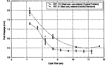
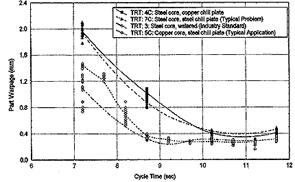
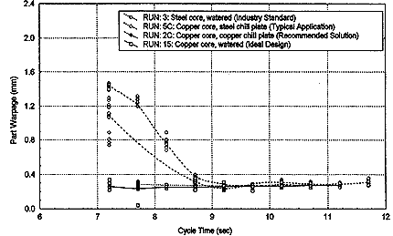
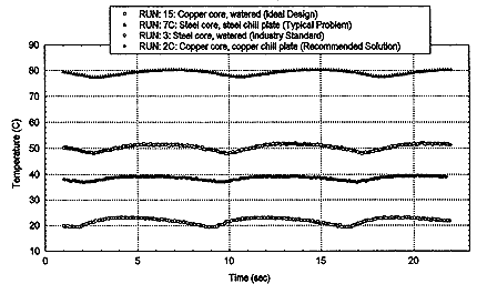
Performance of steel cores is shown in Figure 1. These tests represent the part deformation present at various overall cycle times. With short cycle times, parts deform either through ejection or post-molding shrinkage. With long cycle times, parts are allowed to cool while restrained in the mold cavity and the strength of the part allows adequate transmission of ejector force without part deformation. In this case, the normally watered steel core could be considered the industrial standard. As noted in previous research for this mold, approximately nine seconds of total cycle time is required for minimum part warpage. Notice that with the non-watered steel core that stabilization does not occur until 11 seconds and that total part deformation is greater than that seen with the normally watered core. In Figure 2, copper is applied in the mold in two areas. It can be seen that when a copper alloy chill plate was used with a steel core that it gave marginally improvement to the performance of the system when compared to a nonwatered steel core attached to a steel chill plate. However, when a copper alloy core is used with a steel chill plate, the performance is better than the industrial standard of a normally watered steel core. Minimum part warpage occurs approximately 1/2 second sooner than the normally watered steel core. This scenario represents a typical application fix for hot spots in the tool. Notice the significant change over the previous non-watered steel core on a steel chill plate. In effect, the change not only saved two seconds of cycle time over the non-watered steel core but produces a smaller part warpage comparable to normally watered systems. Figure 3 depicts the best case scenarios as designed into the tool. Besides illustrating the industry standard watered steel core and the typical application of nonwatered copper alloy core attached to a steel chill plate, we see here the profound effect of using a normally watered copper alloy core. The remarkable combination seen here is that is that of a copper alloy core attached to a copper alloy chill plate. Performance of a non-watered copper alloy core attached to copper alloy chill plate is nearly identical in terms of cycle time and net part warpage. Figure 4 illustrates the temperature ranges for a nonwatered steel core with a steel chill plate, a normally watered steel core, a copper alloy core with a copper chill plate and a normally watered copper alloy core. Each hump in the data represents the duration of a single cycle. A series of cycles for each core system were overlaid to produce the graph. The only significant difference between a normally watered copper alloy core and a non-watered copper alloy core using second surface cooling is that the non-watered copper alloy did run 30 degrees hotter than in the normally watered situation. However, the heat transfer rate was still so efficient that it drew down the process heat residual in the product almost as effectively as a normally watered copper system. This phenomenon is shown in Figure 3 with the warpage data for the copper alloy core with copper chill plate and normally watered coppper alloy core.
 Figure 1. Typical application of steel cores in industry Figure 1. Typical application of steel cores in industry |
 Figure 2. Typical application of chill plates(second surface cooling) Figure 2. Typical application of chill plates(second surface cooling) |
 Figure 3. Optimum application of copper alloy cores and chill plates Figure 3. Optimum application of copper alloy cores and chill plates |
 Figure 4. Core temperature profiles Figure 4. Core temperature profiles |
Conclusions
In those situations where water cannot be directed through a core section, the use of a copper alloy chill plate together with a copper alloy core will provide significantly better performance than in any other non-watered combination. Furthermore, although a copper alloy core using second surface cooling may run warmer than a normally watered core, copper's significant heat transfer can produce part warpage and cycle time comparable to that of a normally watered copper system. These data also clearly show that a watered copper system is not only the most efficient at heat removal and reduction of cycle time. This study adds to the body of evidence that clearly points to the need for increased use of copper in core sections of injection molds. In areas where applying water to the core is impractical, copper alloy components should be used in conjunction with copper alloy second surface cooling for maximum potential heat removal. Application of this information should produce an injection mold with the shortest overall cycle time, and minimum part warpage.
References
-
 Engelmann. P., Dawkins, E., Shoemaker J., Monfore, M. (1997). Improved product quality and cycle times using copper alloy mold cores. Journal of Injection Molding Technology, vol. 1 (1). pp. 18-24.
 -
 Engelmann, P., Dawkins, E., Shoemaker, J., Monfore, M. (1996). Applying copper alloys using new mold cooling software. Technical Papers vol. 42, pp. 1000-1005. Brookfield, Ct: SPE.
 -
 Engelmann, P., Dawkins, E., Shoemaker, J., Monfore, M. (1996). Predicting the performance of copper alloy mold cores. Plastics Engineering, vol. 52 (10), pp. 35-37.
 -
 Engelmann, P., Dawkins, E., Monfore, M. (1997). Copper vs. Steel cores: Process performance, temperature profiles and warpage. Technical Papers, vol. 43, pp. 972-976, Brookfield, Ct: SPE.
 -
 Shoemaker, J., Engelmann, P., Dawkins, E. & Kietzmann, C. (1998). Cooling prediction of non-watered copper and steel cores. Technical Papers, vol. 44, pp. , Brookfield, Ct: SPE.
